
27MHz crystal oscillator transmitter simulation in PSPICE
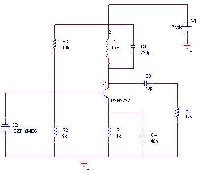
The 27 MHz transmitter circuit typically consists of several key components, including an oscillator, modulator, amplifier, and antenna. The oscillator generates a radio frequency signal at 27 MHz, which serves as the carrier wave for transmission. Commonly, a crystal oscillator or a phase-locked loop (PLL) circuit is employed to achieve stable frequency generation.
The modulator is responsible for encoding the information signal onto the carrier wave. This can be accomplished through amplitude modulation (AM), frequency modulation (FM), or phase modulation (PM), depending on the application requirements. The choice of modulation technique will influence the design of the modulator circuit, which may involve components such as operational amplifiers, diodes, and filters to shape the signal appropriately.
Following modulation, the signal is fed into a power amplifier, which increases the power level of the signal to ensure adequate transmission range. The amplifier circuit design should account for factors such as gain, linearity, and efficiency to maintain signal integrity while minimizing distortion.
Finally, the antenna is a critical component that converts the electrical signal into electromagnetic waves for transmission through the air. The design of the antenna, whether it be a dipole, monopole, or another type, should be matched to the transmitter's output impedance for optimal performance.
In PSPICE, the simulation can be set up by creating a schematic that incorporates these components. Each part of the circuit can be represented using appropriate models, and the simulation parameters can be adjusted to analyze the circuit's behavior under various conditions. The output can be visualized through waveform analysis, allowing for the evaluation of key performance metrics such as frequency stability, modulation fidelity, and transmission range.
By simulating the 27 MHz transmitter circuit in PSPICE, it is possible to identify potential issues and optimize the design before physical implementation, ensuring a more efficient and effective transmitter system.I want to simulate 27MHz transmitter circuit in PSPICE. Circuit diagram is given as Figure-1 in following.. 🔗 External reference
Related Circuits
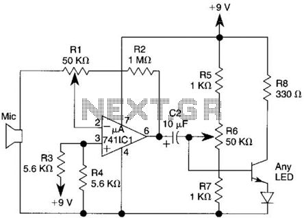
This transmitter utilizes a 741 operational amplifier as a high-gain audio amplifier, which is activated by a microphone. The output of the 741 is connected to Q1, functioning as the driver for an LED. Potentiometer R1 serves as the...
To generate a 1 MHz square wave, it is advisable to use a higher frequency crystal and divide it down for two reasons: (1) 4 MHz crystals are generally more affordable and easier to procure than 1 MHz crystals;...
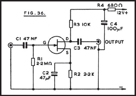
Figure 36 illustrates the circuit of a preamplifier featuring a high impedance input and an output circuit designed for coupling to a main amplifier. This configuration is particularly advantageous for applications such as amplifying the signal from a crystal...
Electronics tutorial about quartz crystal oscillators, including harmonic, overtone, Pierce oscillator, and crystal quartz oscillator circuits. Quartz crystal oscillators are vital components in modern electronics, providing stable frequency references for a variety of applications. They utilize the piezoelectric properties of...

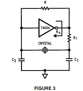
This circuit is guaranteed to oscillate at a frequency of approximately 2.2/(R1 x C) if R2 is greater than R1. Additionally, the number of gates can be reduced further by replacing gates 1 and 2 with a non-inverting gate. The...
This circuit is a crystal oscillator that operates at a frequency of 3.5 MHz. The crystal oscillator circuit utilizes a quartz crystal resonator to generate a stable frequency output. The primary components typically include the crystal, an amplifier (often a...
Warning: include(partials/cookie-banner.php): Failed to open stream: Permission denied in /var/www/html/nextgr/view-circuit.php on line 713
Warning: include(): Failed opening 'partials/cookie-banner.php' for inclusion (include_path='.:/usr/share/php') in /var/www/html/nextgr/view-circuit.php on line 713