
Temperature Controlled Kitchen Exhaust Fan
The circuit for controlling an exhaust fan based on ambient temperature typically includes a temperature sensor, a microcontroller or comparator, and a relay to switch the fan on or off. The temperature sensor, often a thermistor or an LM35, detects the ambient temperature and converts it into an electrical signal. This signal is then fed into a microcontroller or a comparator circuit, which processes the input and determines whether the temperature exceeds a predefined threshold.
When the ambient temperature rises above the set limit, the microcontroller activates a relay, which in turn powers the exhaust fan. The relay serves as a switch that allows the higher voltage required by the fan to be controlled by the lower voltage signal from the microcontroller. Additionally, the circuit may include a potentiometer to adjust the temperature threshold, allowing for customization based on specific kitchen conditions.
For safety and reliability, it is advisable to integrate a fuse in series with the fan to protect against overloads. A diode can also be placed in parallel with the relay coil to prevent back EMF from damaging the microcontroller when the relay is deactivated. The circuit can be powered by a standard AC supply, with appropriate voltage regulation and isolation measures to ensure safe operation.
Overall, this temperature-controlled exhaust fan circuit enhances kitchen ventilation efficiency by automatically activating the fan when necessary, thus contributing to a more comfortable cooking environment.Exhaust fan is an important component in kitchens. Here is a simple circuit to control kitchen fans by monitoring the ambient temperature. It is built arou.. 🔗 External reference
Related Circuits
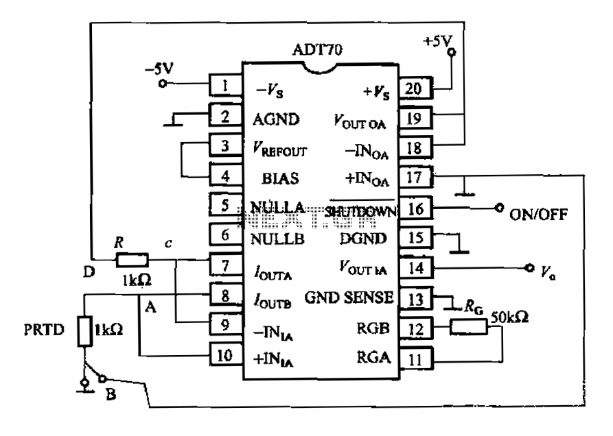
The AD170 basic electrical parameters include a temperature coefficient of 25 ppm/°C and a temperature measurement accuracy of ±1°C, with a maximum temperature range of -200°C to +100°C. The power supply required is +5V or -5V, and the operating...
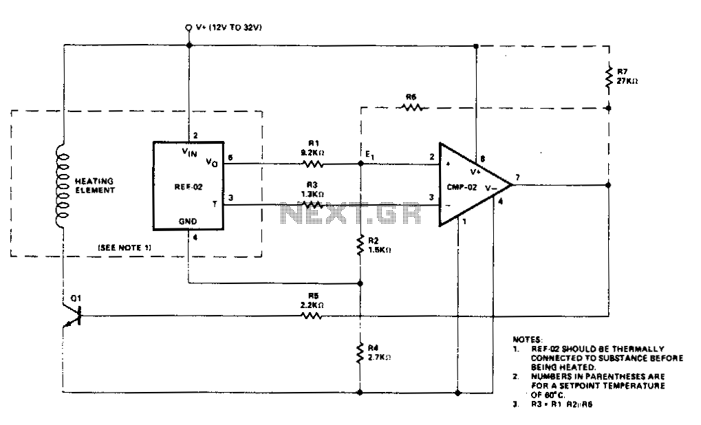
Temperature control is accomplished using the REF-02 +5 V Reference/Thermometer in conjunction with the CMP-02 Precision Low Input Current Comparator. The CMP-02 activates a heating element driver (Q1) whenever the current temperature falls below a predetermined setpoint, which is...
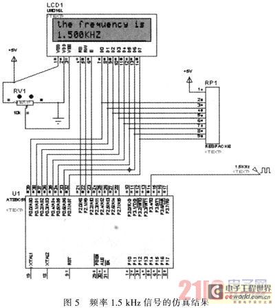
The primary function of the frequency counter is to measure the frequency and cycle of a signal. Its applications span a wide range, extending beyond simple instrument measurements to areas such as education, scientific research, high-precision instrument measurement, and...
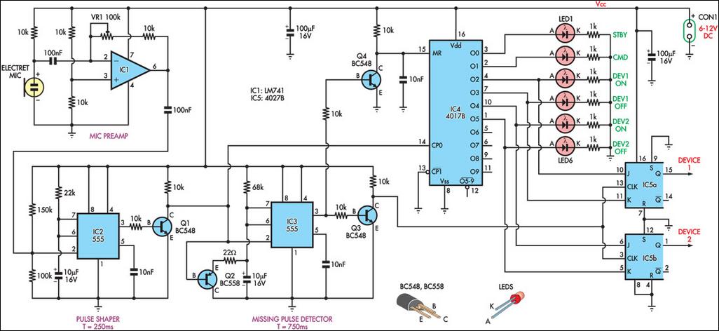
This circuit can switch two or more devices on and off in response to a series of rapid handclaps. The claps are detected by an electret microphone and amplified by a 741 operational amplifier (IC1). IC1 is configured as...
A thermistor placed in the specified position creates a heat-activated sensor. Variations in temperature will modify the output of the operational amplifier (op-amp), activating the relay and illuminating the LED. Interchanging the positions of the thermistor and the 47k...
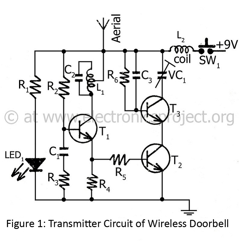
The controlling range of the wireless doorbell is 100 meters. The transmitter section is designed around an oscillator transistor (BF194B) T2, which is followed by two transistors (BC148) T1 and T3. Transistor T2 generates a specific radio frequency determined...
Warning: include(partials/cookie-banner.php): Failed to open stream: Permission denied in /var/www/html/nextgr/view-circuit.php on line 713
Warning: include(): Failed opening 'partials/cookie-banner.php' for inclusion (include_path='.:/usr/share/php') in /var/www/html/nextgr/view-circuit.php on line 713