
Dimmable Fluorescent Lights Bulbs
The described dimmable fluorescent light circuit incorporates several key components to achieve both the starting and brightness adjustment of fluorescent tubes. At its core, the circuit includes a choke coil, which is essential for creating the necessary high voltage to ignite the fluorescent tube. The choke coil works by inducing a back EMF (electromotive force) when current is interrupted, thus generating the required voltage spike.
In addition to the choke, the circuit features a starter component that can be a thermal or electronic starter. This component is responsible for momentarily allowing a high current to flow through the filaments of the fluorescent tube, thereby heating them up to facilitate the ionization of the gas within the tube. After the tube ignites, the starter disconnects, allowing the tube to operate at the lower supply voltage.
The brightness control potentiometer, P1, is a variable resistor integrated into the circuit, allowing users to adjust the amount of current flowing through the fluorescent tube. By altering the resistance, the potentiometer can effectively control the brightness of the light emitted. When initially powering the circuit, it is crucial to set the potentiometer to its maximum position to ensure the tube receives enough current to start properly.
Overall, the design of this dimmable fluorescent light circuit not only improves the usability of fluorescent lighting by allowing for brightness adjustments but also simplifies the starting process by integrating the functions of traditional starters within the circuit. This results in an efficient and user-friendly solution for controlling fluorescent lighting in various applications.The brightness of a fluorescent light bulb or neon tube cannot adjust as easily as that of a incandescent bulb because it starts only when a voltage is much higher than that of the network, then remains on at electrical network voltage. Normally, the high starting voltage is obtained by the interruption of current that circulates through a choke c
oil. This is usually a starter to ensure a sufficiently large current through the tube filaments. These starter functions are taken over by this dimmable fluorescent light circuit presented which also allows adjustment of the fluorescent bulbs brightness. When we switch on the neon tube, the brightness control potentiometer, P1, should be placed on the position of maximum brightness, in order to facilitate the start.
🔗 External reference
Related Circuits
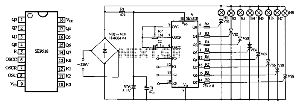
The circuit utilizes a 220V AC input, which is processed through a VD1-VD4 bridge rectifier to convert the AC voltage into a DC voltage. This DC voltage is then used to power eight lights labeled H1 to H8. Additionally,...
When the tank is cleaned the fish are removed and placed in a small amount of the tank water. The problem is that fish don’t like rapid temperature fluctuations. A simple in-tank or stick-on thermometer would have sufficed, but...

The circuit utilizes a 555 timer IC to create a lighting group delay effect, as illustrated in Figure 2-46. It consists of the 555 IC along with a resistor and capacitor configuration that establishes the delay. The circuit remains...

This simple circuit drives six LEDs in a "Knightrider scanner mode." Power consumption primarily depends on the type of LEDs used, particularly when utilizing a 7555 (the CMOS version of the 555 timer). The circuit is designed to create a...
This device functions as a simple timer that keeps the vehicle's headlights on for approximately 1 minute and 30 seconds, allowing access to dark areas without the need to return and switch off the lights. Pressing switch P1 enables...
Auto repair service for Mercedes 300SD backup lights. The backup lights in a Mercedes 300SD serve a crucial function by illuminating the area behind the vehicle when it is in reverse gear. This feature enhances visibility for the driver and...