
SE9518 holiday lights ASIC
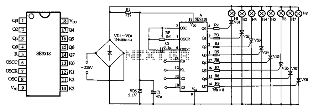
The circuit operates by first converting the 220V AC input into a usable DC voltage through the bridge rectifier formed by diodes VD1 to VD4. This conversion is essential for providing a stable power supply to the subsequent components. The output from the rectifier is typically a pulsating DC voltage, which is then smoothed by the filter and regulated by diode VD5. The voltage drop across resistor RI is crucial for ensuring that the voltage levels are appropriate for the lights and control circuitry.
The thyristors (VS1 to VS8) are key components in managing the power delivered to the lights. Each thyristor is driven by its corresponding output (Q0 to Q7) through resistors (R2 to R9), which limit the current and protect the components from excessive current flow. The thyristors allow for the control of the lights by switching them on and off rapidly, enabling various flashing patterns as determined by the programming options available at terminals KO to K3.
The design provides flexibility, as users can modify the connections and programming according to their requirements. By consulting the referenced Table 2-23, users can configure the circuit to achieve different lighting effects, enhancing the versatility of the system. The ability to customize the flashing modes of the lights H1 to H8 makes this circuit suitable for various applications, including decorative lighting, signaling, or any scenario where dynamic light patterns are desired.220V AC by VD1-VD4 bridge rectifier, all the way to eight lights H1 ~ H8 supply of electricity, the other passing RI drop pressure, VD5 regulator and filter cl A power supply m anifold. Manifold eight outputs Q0-W via resistors R2-R9 direct drive thyristor VS1 ~ VS8. FIG pattern programmed end KO ~ K3 are vacant did not answer, according to the reader Table 2-23 shows the connection according to their own requirements, you can make eight Tsui lights Hl ~ H8 flashes according to the set mode.
Related Circuits
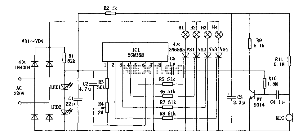
This document describes a family karaoke lighting design that employs various methods to control the circuit. The control circuit presented here features a four-way light output with loop jumping and speed control capabilities. The practical circuit utilizes a microphone...
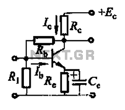
Basic reference transistor bias circuit - Mixed Negative feedback The basic reference transistor bias circuit utilizing mixed negative feedback is a fundamental electronic configuration designed to stabilize the operating point of a transistor. This circuit typically employs a combination of...
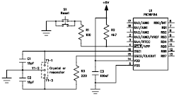
A basic circuit of the 89C2051 shown here can be made easily using point-to-point soldering with a universal PCB. Use an ordinary 20-pin socket, do not use a circle-pin socket. D1 is a small dot LED. U2 can be...
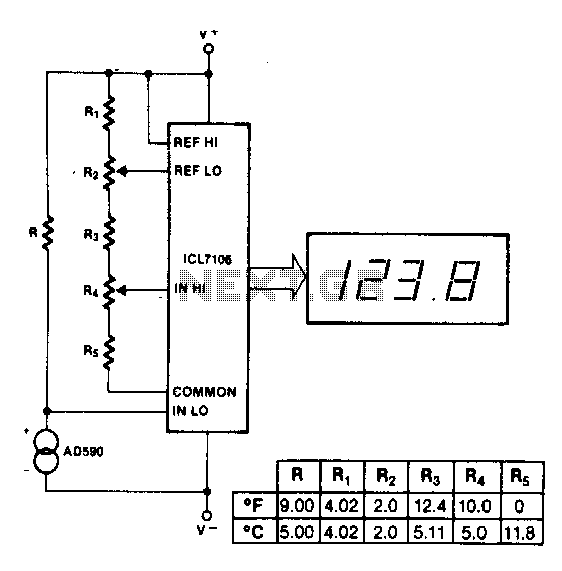
The maximum reading on the Celsius range is 199.9 °C, which is limited by the short-term maximum allowable sensor temperature. The maximum reading on the Fahrenheit range is 199 °F (93 °C), constrained by the number of display digits....
The following file contains detailed information about the design of a basic clock oscillator circuit diagram. Included in this file is information about selecting the components. The clock oscillator circuit is a fundamental component in various electronic systems, providing a...

The circuit activates a light corresponding to the first button pressed in a "Who's First" game. Three stages are illustrated, but the circuit can be expanded to accommodate any number of buttons and lamps. The described circuit operates as a...