
car headlights timer schematics
The schematic for this timer circuit can be designed utilizing standard electronic components. The core components include a 12V battery, a capacitor (C1), resistors (R1), transistors (Q1 and Q2), a relay (RL1), and a diode (1N4002).
The circuit operates as follows: When the user presses switch P1, capacitor C1 begins to charge through resistor R1. The charging time is dictated by the RC time constant, which is determined by the values of R1 and C1. Once C1 reaches a sufficient voltage, around 0.7V, it activates Q1, turning it on. This action allows current to flow to Q2, which energizes the relay RL1, closing its contacts and powering the vehicle's headlights.
The headlights remain lit as long as the relay is activated. The discharge of C1 occurs through R1 and the load of the circuit, which includes the base-emitter junction of Q1. The headlights will stay on until C1 discharges to a voltage below 0.7V, at which point Q1 turns off, deactivating Q2 and opening the relay contacts, thus turning off the headlights.
For the alternative configuration using the interior lamp, the diode 1N4002 allows current to flow from the interior lamp to charge C1 when the door is open. When the door is closed, the current path is interrupted, and C1 begins to discharge, activating the headlights in the same manner as described previously.
This circuit provides a practical solution for users who frequently find themselves in dark environments, ensuring that their headlights remain on without the need for manual operation. The use of common components allows for easy assembly and integration into existing vehicle systems.This device is a simple timer, allowing to keep on the headlights of your vehicle for about 1min. and 30sec. , e. g. when accessing some dark place, without the necessity of coming back to switch-off the lights. Pushing on P1 allows C1 charging to full 12V battery supply. Therefore Q1 is driven hard-on, driving in turn Q2 and its Relay load. The hea dlights are thus activated by means of the Relay contact wired in parallel to the vehicle`s headlights switch. RL1 remains activated until C1 is almost fully discharged, i. e. When its voltage falls below about 0. 7V. The timing delay of the circuit depends by C1 and R1 values and was set to about 1min. and 30sec. In practice, due to electrolytic capacitors wide tolerance value, this delay will vary from about 1min.
and 30sec. to 1min. and 50sec. An interesting variation is to use the inside lamp as a command source for the timer. In this way, when the door is opened C1 is charged, but it will start to discharge only when the door will be closed, substituting pushbutton operation. To enable the circuit acting in this way, simply connect the cathode of a 1N4002 diode to R1-C1 junction and the anode to the "live" lead of the inside lamp.
This lead can be singled-out using a voltmeter, as it is the lead where a 12V voltage can be measured in respect to the vehicle frame when the lamp is on. 🔗 External reference
Related Circuits
The Park Aid system utilizes three LEDs to indicate the distance of a bumper barrier through infrared operation, designed for indoor use. The circuit diagram includes the following components: R1 (10K 1/4W resistor), R2, R5, R6, R9 (1K 1/4W...
The project originated from a request by Tony Bowler, a member of the Long Eaton Club, who sought assistance in converting a "Golden Oldie" model to electric free-flight. He selected Vic Smeed's "Debutante" to be powered by seven AE...
This timer is designed to automatically switch off a portable radio after a set period, allowing users to relax without worrying about battery drain. Resistor R1 and capacitor C1 create a long time constant. When switch P2 is momentarily...
This circuit provides a visual 9-second delay using a 7-segment digital readout LED. When the switch is closed, the CD4010 up/down counter is preset to 9, and the 555 timer is disabled, holding the output high. When the switch...
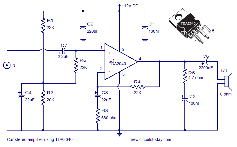
A car stereo amplifier circuit utilizing the TDA2040 is presented here. The TDA2040 is a monolithic integrated audio amplifier that functions in Class AB mode. This integrated circuit features built-in short circuit protection and thermal shutdown capabilities, and it...
The issue with sound cards is that they typically bandpass their input signals, making it challenging to record signals below 20Hz. Two potential solutions exist. The first involves modifying the sound card to eliminate the high-pass filter that blocks...