
direct coupled discrete astable
The described circuit functions as an astable multivibrator, which is a type of oscillator that generates a continuous square wave output without requiring any external triggering. The circuit is composed of two NPN transistors, configured in such a way that their outputs are connected to the inputs of the other, creating a feedback loop that sustains oscillation. The direct coupling of the bases and collectors allows for efficient signal transfer between the two transistors.
In this configuration, the capacitors connected to the emitters (C1 and C2) play a crucial role in determining the frequency of oscillation. The values of these capacitors, along with the resistors in the circuit, set the timing characteristics of the output waveform. When the circuit is powered, one transistor will turn on, causing the other to turn off, and vice versa, resulting in a continuous oscillation.
The output waveform produced by this circuit is not a perfect square wave; instead, it resembles a triangular wave due to the charging and discharging characteristics of the capacitors. This triangular wave can be beneficial in applications where a linear ramp signal is required. The use of a single 0.1 µF capacitor between the emitters simplifies the circuit while still achieving the desired oscillation effect.
In practical applications, this type of astable multivibrator can be used in timers, pulse width modulation, and signal generators. Careful selection of the resistor and capacitor values allows for precise control over the frequency and duty cycle of the output waveform, making this circuit versatile for various electronic projects. Additionally, the reliability of the transistor switching characteristics ensures stable operation over a range of conditions, which is critical in many electronic designs.This flip-flop circuit is a free running/astable multivibrator one, with bases and collector of both emitter biased transistor are directly coupled to each other. Switching action is supported by means of capacitor in each emitter circuit. This configuration produce a triangle waves at emitters. Since neither transistor can remain permanently cut off, then a free running oscillation will be generated. We can use single 0. 1 uF capacitor between emitters in place of C1 and C2. 🔗 External reference
Related Circuits
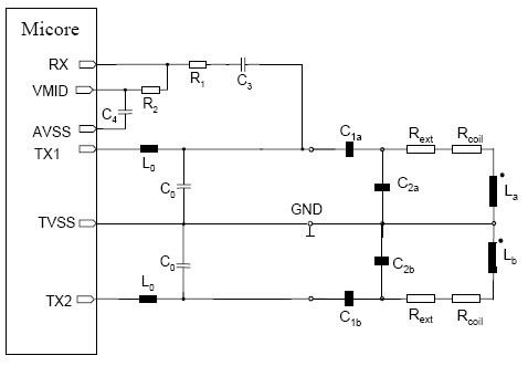
This document provides guidance on designing an antenna for the MICORE contactless reader IC family, which includes the MF RC500, MF RC530, MF RC531, SL RC 400, and CL RC 632. The antenna design and matching process is consistent...
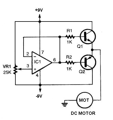
The DC motor driver circuit depicted in the images can be utilized for controlling DC motors, allowing for bidirectional rotation and adjustable speed. This straightforward circuit is constructed using a 741 operational amplifier (op-amp) as a voltage comparator, along...
The bi-directional sequencer employs a 4-bit binary up/down counter (CD4516) along with two "1 of 8 line decoders" (74HC138 or 74HCT138) to create the well-known "Night Rider" display. A Schmitt Trigger oscillator generates the clock signal for the counter,...
A Coil Coupled Operation Metal Detector made from readily obtainable components and using an ordinary medium receiver as a detector. The metal detector shown here may well represent a new genre. At any rate, after some exposure, it is...
For controlling a small DC motor, such as the one found in a tape recorder, Q1 and Q2 are in saturation when both points A and B are HIGH. Component: .. To control a small DC motor effectively, a circuit...

The main requirements are a directional antenna, such as a ferrite rod or frame, and a screened case for the equipment. In the past, some competitors modified standard medium wave receivers to operate on the 160m band by retuning...