
Micore Reader IC Family Directly Matched Antenna Design
Designing an effective antenna requires an understanding of the numerous parameters that impact its overall performance, necessitating basic RF knowledge. However, a complete antenna design can be accomplished without extensive RF-specific expertise. The design process is divided into two levels: the basic parameter design, which caters to individuals less familiar with RF design tools, and the full parameter design, aimed at those seeking to address all specific design requirements for optimal performance.
The basic parameter design involves certain fixed requirements and parameters, producing an optimized antenna. Guidelines, necessary formulas, and design support tools are provided. While this design may not fully comply with ISO/IEC14443, it meets the requirements for Mifare and I-Code. The full parameter design focuses on achieving full ISO/IEC14443 compliance, including support for higher bit rates, and encompasses all adjustable parameters, background information, and the overall behavior of the antenna.
Appendix 6.1 contains a checklist for optimizing and finalizing antenna designs for proximity readers based on the Micore, along with relevant formulas and an example design. In this context, "card" refers to a contactless smart card per ISO14443 (or MIFARE) or a contactless tag/label per ISO15693 (or I-Code). The Micore reader IC family is engineered to achieve operational distances of up to 100 mm without requiring external amplifiers.
The design rules and parameters are fundamentally similar for ISO14443, Mifare®, ISO15693, and I-Code®, allowing the same antenna to interface with all mentioned products. A complete antenna design encompasses the antenna coil and resonance circuit design, matching of the antenna circuit, receiving circuitry, and EMC filtering. While some blocks may utilize only a few passive components, it is crucial to account for all blocks and their functionalities to ensure the antenna operates effectively.
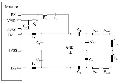
The transmit power must be maximized while adhering to radiation and datasheet limits, particularly concerning harmonic radiation up to 1 GHz. The transmit data, whether 10% or 100% Amplitude Shift Keying (ASK) modulated, must be transmitted effectively to ensure all cards can receive it. The signal shape and timing, including the Q-factor, are critical considerations. The complete antenna circuitry typically comprises eight capacitors, two inductors, two or four resistors, and a symmetrical antenna coil (La + Lb), as illustrated in the provided schematic.How to design an antenna for the MICORE contactless reader IC family. (The MIFORE reader IC family includes the MF RC500, MF RC530, MF RC531, SL RC 400 and the CL RC 632. The antenna design and matching is the same for all of these ICs. ) For a good overview the Micore Antenna Principle section shows the blocks of each reader antenna design, how these blocks fit to Micore, and also the complete schematic of a Micore Antenna. Because there are many parameters that influence the overall performance of an antenna, a basic RF knowledge is needed to design an antenna that takes all these parameters into account. Although this (specific) knowledge is important for understanding the background, a complete antenna design can be done without RF-specific knowledge.
Therefore the complete design of a directly matched antenna is divided into two design levels: The basic parameter design is dedicated to those, who are not really familiar with RF design and its tools. Although a certain number of requirements and parameters are frozen, the design will yield an optimized antenna.
A guideline, the required formulas, and a tool to support the design is described and provided. Depending on some simplifications this design might not be completely compliant to the ISO/IEC14443, even though it fully satisfies the Mifare and I-Code requirements. The full parameter design is dedicated to those, who want to cover all the specific cases of various design requirements to make a perfect design for the application.
This design describes how to build an antenna, which is fully ISO/IEC14443 compliant (including the higher bit rates). The complete antenna design covers all the open parameters, some background information for the design, and the general behaviour of such an antenna.
Appendix 6. 1contains a checklist to help optimizing and finishing an antenna design for a proximity reader based on the Micore. It also contains a collection of relevant formulas and an antenna design example. ”Card in this document means a contactless smart card according to the ISO14443 (or MIFARE) or a contactless tag / label according to the ISO15693 (or I-Code).
The Micore is a single reader IC family designed to achieve operating distances up to 100mm without external amplifiers. The design rules and parameters are basically the same for ISO14443, Mifare ®, ISO15693 and I-Code ®, i.
e. the same antenna can be used to communicate with all products mentioned. A complete antenna design always includes the antenna coil and resonance circuit design, the matching of the antenna circuit, the receiving circuitry and the EMC filtering. Although some of theses blocks may contain only a few passive components, it is important to consider all these blocks and all their functionality to guarantee the proper working of the complete antenna.
Transmit power: The radiated magnetic field has to be maximized considering the radiation and datasheet limits, especially the limits for the radiation of the harmonics (up to 1GHz). Transmit data: The 10% or 100% ASK modulated data signal has to be transmitted in such way, that every card is able to receive it.
The signal shape and timing (i. e. the Q-factor) has to be considered. Basically this complete antenna circuitry consists of 8 capacitors, 2 inductors, 2 or 4 resistors and the symmetrical antenna coil (La + Lb) as shown in Fig 2. 🔗 External reference
Related Circuits
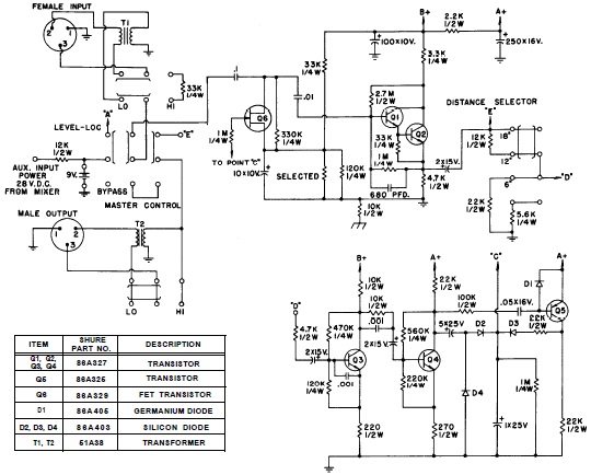
SHURE is an American corporation that manufactures consumer and professional audio electronics, including microphones, phonograph cartridges, and discussion systems. SHURE Incorporated is a well-established entity in the audio electronics industry, recognized for its innovative design and high-quality products. The company...
Bold lines indicate soldered connections, while arrows represent wire-based connections. Red indicates V_cc, black represents ground, blue signifies intermediate connections, and gold denotes the primary output. Pins 1 and 5 are connected to ground. It is noted that pin...
Application note on designing linear and switch-mode (switching DC-DC converter current source) battery charger applications that require external microcontrollers and related system-level issues for notebook computers. The application note provides guidance on the design of both linear and switching DC-DC...
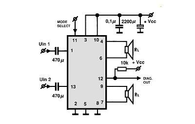
A simple Class B power amplifier can be constructed using the TDA8560 audio integrated circuit (IC). The TDA8560 amplifier features an internally fixed voltage gain, ensuring excellent channel balance. This audio amplifier project is capable of delivering dual 40-watt...
A very simple controller circuit with impressive performance. If a fully automatic computer-controlled rotator is not affordable but enhanced capability is desired from a basic rotator, the ZL1BPU Rotator Controller offers a simple "point and shoot" computer-controlled antenna solution....
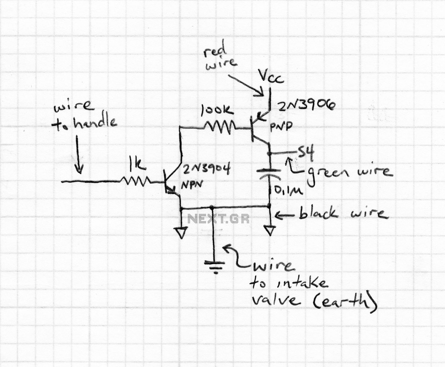
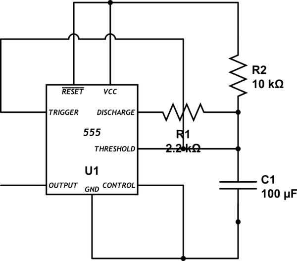
Magnetic stripe reader, electric circuit theory, logic operation. The wiring diagram does not connect the transistor in the circuit. The collector pin of the transistor connects to the tip pin of the jack. The base pin of the transistor...
Warning: include(partials/cookie-banner.php): Failed to open stream: Permission denied in /var/www/html/nextgr/view-circuit.php on line 713
Warning: include(): Failed opening 'partials/cookie-banner.php' for inclusion (include_path='.:/usr/share/php') in /var/www/html/nextgr/view-circuit.php on line 713