
Direction and speed control
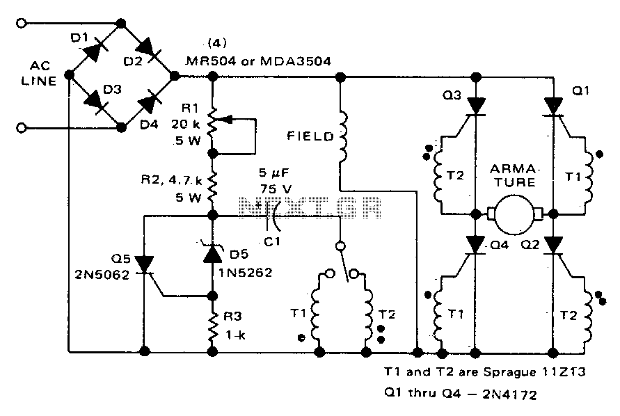
The described circuit utilizes a Silicon Controlled Rectifier (SCR) bridge configuration to control a DC motor's operation. In this setup, the motor's field winding is connected to a rectified DC supply, providing a constant magnetic field. The SCR bridge, which consists of four SCRs arranged in a full-bridge configuration, allows for control of the armature current. By adjusting the firing angle of the SCRs, the effective voltage applied to the armature can be varied, enabling speed control.
The use of a potentiometer, designated as R1, directly influences the firing angle of the SCRs. By varying the resistance of R1, the control circuit alters the phase delay at which the SCRs are triggered, thus modifying the average voltage supplied to the armature. This adjustment not only controls the speed of the motor but also facilitates direction reversal. By changing the triggering sequence of the SCRs, the polarity of the voltage across the armature can be reversed, allowing the motor to rotate in the opposite direction.
This circuit design is particularly advantageous in applications requiring precise speed and direction control, such as in robotics and conveyor systems. The combination of a unidirectional field current and a reversible armature current provides flexibility in operation while maintaining efficient performance. Proper thermal management and component ratings must be considered to ensure reliable operation, especially in high-load scenarios.This circuit operates like the one shown in Fig, 57-4, The only differences are that the field is placed across the rectified supply and the armature is placed in the SCR bridge. Thus the field current is unidirectionali)ut armature current is reversible; consequently the motor"s direction of rotation is reversible
Potentiometer Rl controls the speed. 🔗 External reference
Related Circuits
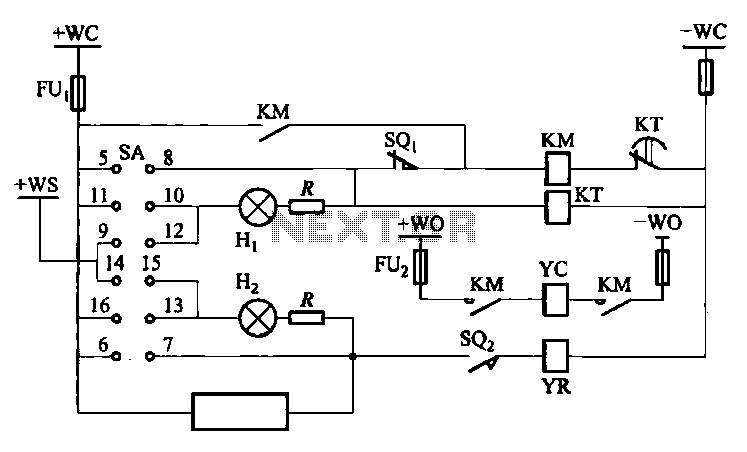
The DW10M de-excitation type switch is based on the DW10 automatic air circuit breaker, transitioning from normally open to normally closed contact. The models available include DW10M-200, DW10M-400, and DW10M-600. The control circuit for this type switch is illustrated...
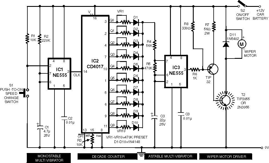
Wiper Speed Control. A continuously operating wiper in a vehicle can be bothersome, particularly during light rain. The circuit described here allows for the adjustment of the wiper's sweeping rate, ranging from once per second to once every ten...
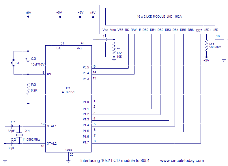
Interfacing a 16x2 alphanumeric LCD module with the AT89S51 microcontroller. The circuit diagram, theory, and program are included. JHD162 LCD module pinout and commands are provided. The integration of a 16x2 alphanumeric LCD module with the AT89S51 microcontroller involves several...
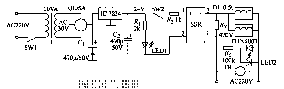
An AC solenoid-driven control circuit utilizing the SSR principle is illustrated. When switch SW1 is closed, a 220V AC transformer steps down the voltage to 30V AC through transformer T. The circuit includes a rectifier, capacitor C, and a...
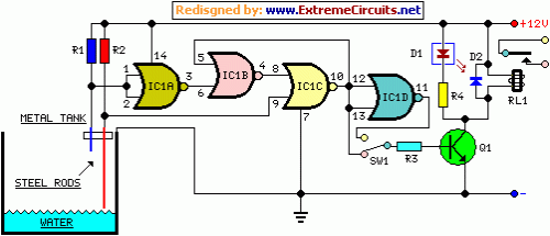
This circuit utilizes a relay to control a water pump, enabling automatic level management of a water reservoir or well. The shorter steel rod functions as the "water high" sensor, while the longer rod serves as the "water low"...
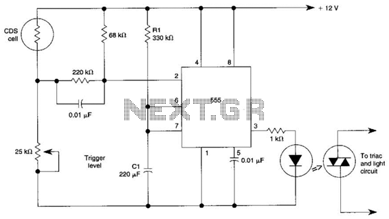
This circuit can control the on/off cycle of a light using a CDS photocell and turn it off after a preset period. The light can only be activated when the CDS cell is in darkness, and it remains on...