
Wiper Speed Control
The wiper speed control circuit typically employs a variable resistor or potentiometer to adjust the timing of the wiper motor operation. This circuit can be implemented using a simple timer IC, such as the NE555, configured in astable mode, to generate a square wave output that drives the wiper motor.
The key components of the circuit include the NE555 timer, a motor driver (such as a transistor or a relay), a potentiometer for speed adjustment, and capacitors for timing control. The potentiometer alters the resistance in the timing circuit, thereby changing the duty cycle of the output signal. This adjustment directly influences how often the wipers sweep across the windshield.
In the astable configuration, the NE555 timer continuously oscillates between its high and low states, which can be set to correspond to the desired wiper speed. The output from the NE555 can be fed into a transistor, which acts as a switch to control the wiper motor. The motor will then operate at the speed determined by the timing circuit, allowing the driver to set a comfortable wiper frequency based on the current weather conditions.
Additionally, diodes can be incorporated to protect the circuit from back EMF generated by the motor, ensuring the longevity and reliability of the wiper speed control system. This setup enhances the driving experience by providing customizable wiper functionality, adapting to varying levels of precipitation.Wiper Speed Control. A continuously working wiper in a car may prove to be a nuisance, especially when it is not raining heavily. By using the circuit described here one can vary sweeping rate of the wiper from once a second to once in ten seconds
🔗 External reference
Related Circuits

This is a simple hobby circuit for a remote-controlled toy car. The primary component utilized is the IR sensor circuit, which includes a TSOP IR receiver. This receiver allows the user to start and stop the DC motor of...
Both halves of the circuit are identical. Both inputs have a DC path to ground via the input 47k control, which should be a dual logarithmic type potentiometer. The balance control is a single 47k linear potentiometer, which, when...
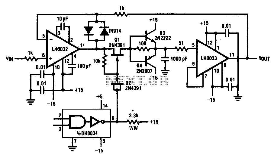
This circuit demonstrates a 10 V acquisition time of 900 ns with 0% accuracy and a droop rate of only 100 µV/ms at an ambient temperature of 25°C. A faster acquisition time can be achieved by using a smaller...
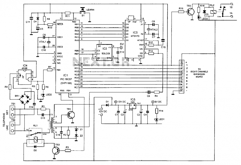
This device enables remote control of various appliances (up to eight with suitable add-on expansion boards) such as lights, water heaters, air conditioning, plant watering systems, alarms, etc., via a relay. It allows users to perform actions such as...
Circuit of a crystal-controlled FM transmitter. The circuit utilizes a crystal oscillator and several power amplifier stages to enhance output power. The crystal-controlled FM transmitter circuit is designed to generate frequency-modulated signals with high stability and precision. At the core...
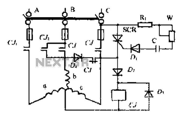
AC contactor controls suction units, with the motor activated simultaneously. A pair of contacts (CJ1) short-circuits the thyristor (SCR), turning it off. The contactor (C) is influenced by the diode's DC voltage. In the positive half-wave power cycle, the...