
Discharge before memory circuit
The discharge before memory circuit serves a crucial role in digital electronics, particularly in applications where precise timing and state management are essential. This circuit typically incorporates a delay reset mechanism that ensures the memory element does not respond to input signals instantaneously.
The circuit design often includes a timing component, such as a resistor-capacitor (RC) network, which defines the delay period. Upon receiving an input signal, the timing mechanism initiates, allowing the circuit to maintain its output state for the duration of the delay. This ensures that transient input signals do not inadvertently alter the memory state, thus providing stability and reliability in signal processing.
In practical implementations, the delay reset circuit can be configured using various components, such as operational amplifiers, flip-flops, or dedicated timer ICs, depending on the complexity and requirements of the application. The output signal, which remains stable during the delay period, is typically connected to subsequent stages in a digital system, ensuring that downstream components receive a consistent and accurate representation of the desired state.
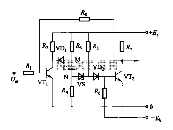
In summary, the discharge before memory circuit, with its delay reset functionality, is integral to achieving controlled operation in digital systems, effectively managing input signals and ensuring that memory circuits function as intended without unintended disruptions.Discharge before memory circuit Before the memory circuit is considered instantaneous action, the delay reset circuit. When the input signal to one that is action, and start ti ming, after after a delay, the circuit returns to the original state. During this period, regardless of whether the input signal is persistent, the circuit remains operation state, and the output signal.
Related Circuits
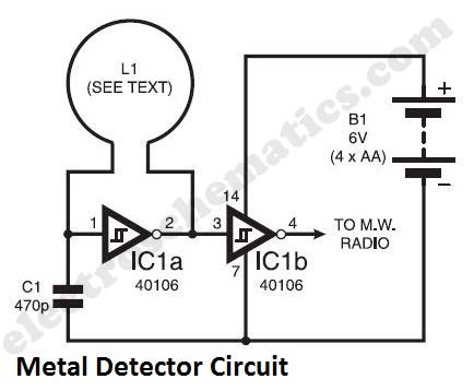
The metal detector circuit presented here exemplifies simplicity while demonstrating effective functionality. It utilizes a single 40106 hex Schmitt inverter IC, a capacitor, a search coil, and batteries. A connection from IC1b pin 4 must be made to a...
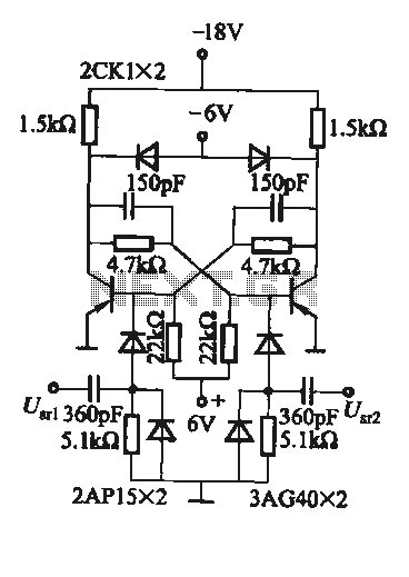
A flip-flop circuit with a memory function for pulse signals. It features two stable states: one where transistor VTi is off and VTZ is conducting, and another where VTi is conducting and VT2 is off. An external signal is...
This PWM controller circuit is suitable for managing small motors with a maximum current consumption of 2A. For higher currents, additional cooling is required. The PWM (Pulse Width Modulation) controller circuit is designed to efficiently control the speed of small...
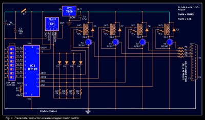
Stepper motors are widely used in applications such as process control, machine tools, and robotics. In particular, remote control of stepper motors is essential in robotics and process control. This document provides the circuit diagrams for both the transmitter...
This circuit design features a modular arrangement that enables users to select only the modules best suited to their needs, allowing for the construction of a chain ranging from one to five modules in length. For those seeking a...
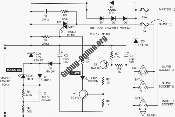
A light dimmer circuit is utilized to adjust the brightness of a lamp to various levels. This dimmer circuit is designed specifically for incandescent lamps, and it is not suitable for use with fluorescent lamps. The light dimmer circuit typically...
Warning: include(partials/cookie-banner.php): Failed to open stream: Permission denied in /var/www/html/nextgr/view-circuit.php on line 713
Warning: include(): Failed opening 'partials/cookie-banner.php' for inclusion (include_path='.:/usr/share/php') in /var/www/html/nextgr/view-circuit.php on line 713