
PC Based Wireless Stepper Motor control Circuit PCB
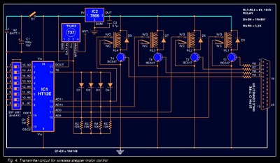
The RF transmitter and receiver modules used for this remote control system are sourced from Alpus India, Mumbai, specifically the AM/ASK type RF transmitter TX-433. The circuit diagram of the transmitter for wireless stepper motor control is depicted. The receiver address is configurable using an 8-way DIP switch (SW1). When a switch contact is open, the corresponding pin is at logic 1, and when closed, it is at logic 0. The data pins are pulled high with resistors R2 through R5. When pin 2 of the parallel port is activated, transistor T1 enters saturation, energizing relay RL1. Consequently, pin 10 (AD8) goes low, sending a logic 0 at that data position while the other data pins remain in a logic 1 state. The logic circuitry at the receiver-decoder interprets the data to control the stepper motor.
The circuit of the receiver and decoder for wireless stepper motor control is also illustrated. Assuming that the encoder and decoder addresses are identical, when any data pin of the PC's parallel port on the transmitter side is low, the corresponding data pin of the decoder will also go low. The data outputs (D8 through D11) from HT12D are routed to inverters N1 through N4, which connect to the ULN2003 driver. The low output from ULN2003 activates the stepper motor. Upon receiving any data, the valid transmission (VT) pin activates, saturating transistor T5 and illuminating LED1. The software for the user interface is developed in C language, with signals generated by the outport() function. The stepper motor's rotation speed can be adjusted by modifying the delay() function argument, and the rotation direction is controlled by a switch function. When the program (WSTEPPER.C) is executed, a welcome message is displayed. Pressing any key leads to the main screen, which presents three options. Pressing the 'c' key rotates the stepper motor clockwise, while pressing the 'a' key rotates it counterclockwise. The program can be exited by pressing the 'q' key.Stepper motors find lots of applications in process control, machine tools and robotics. Especially in robotics and process control, bit is necessary to control the stepper motor from a remote place. Here you will get the transmitter and receiver circuit diagrams and Full source code for the application program.
Here we describe how to wirelessly control a stepper motor from a remote place by using RF modules. For this wireless stepper-motor control system, you need to design and develop the required hardware and software. The parallel port of the PC is used to control the direction of the stepper motor at the transmitter side.
RF interface is used instead of IR to overcome all the drawbacks of the IR interface. The PC signals are transmitted from the RF transmitter and received by the RF receiver. Fig. 1 shows the block diagram for PC-based wireless control of a stepper motor. The signals from the parallel port of the PC are interfaced to the RF transmitter through an encoder. The encoder continuously reads the status of the relay switches, passes the data to the RF transmitter and the transmiter transmits the data.
At the receiving end, the RF receiver receives this data and gives it to the decoder. The decoder converts the single-bit data into four-bit data and presents to the stepper-motor driver. Now, the driver per- Encoder HT12E has eight address and another four address/data lines. The data set on these twelve lines (address and address/data lines) is serially transmitted when transmit-enable pin TE is taken low.
The data output appears serially on DOUT pin. It is transmitted four times in succession. The data consists of differing for 1. ` The frequency of these pulses may lie between 1. 5 and 7kHz depending on the resistance value between OSC1 and OSC2 pins. The internal oscillator frequency of decoder HT12D is 50 times the oscillator frequency of encoder HT12E. The values of timing resistors connected between OSC1 and OSC2 pins of HT12E and HT12D, for the given supply voltages, can be found out from the graphs given in the datasheets of the respective chips.
The resistance values used in the circuits are chosen here for approximately 3kHz frequency of the encoder (HT12E) at Vcc of 9V and 150 kHz of the decoder (HT12D) at Vcc of 5V. matches the levels on A0 through A7 pins four times in succession, the valid transmission pin (VT) is taken high.
The data on pins AD8 through AD11 of the HT12E appear on pins D8 through D11 of the HT12D. Thus the device acts as a receiver of 4-bit data (16 possible codes) with 8-bit addressing (256 possible channels). Once the frequency of the pair is aligned, then on ground of any data pin of the encoder, LED1 of the decoder should glow.
You can also check the transfer of data on pins AD8 through AD11, which is latched to D8 through D11 pins of the decoder once TE pin is momentarily taken low by grounding it through diodes D1 through D4. RF transmitter and receiver: RF transmitter and receiver modules from Alpus India, Mumbai, have been used for RF remote control.
The RF transmitter TX-433 is AM/ASK type. Transmitter: Fig. 4 shows the circuit of the transmitter for wireless stepper motor control. The receiver address to be transmitted can be set with the help of 8-way DIP switch SW1. When any of the switch contacts is open the respective pin will be at logic 1, and when any of the switch contacts is closed the respective pin will be at logic 0. The data pins are pulled high via resistors R2 through R5. When pin 2 of the parallel port goes high, transistor T1 is driven into saturation and relay RL1 energises.
Pin 10 (AD8) goes low through relay RL1 contacts and a 0` is sent at that data position, while other data pins repre-sent logic-1 state. The logic circuitry at the receiver-decoder end decodes the data appropriately for controlling the Receiver and decoder : Fig.
7 shows the circuit of the receiver-cum-decoder for wireless stepper motor control. Assuming that identical address is selected on the encoder and decoder, when any of the data pins of the PC`s parallel port on the transmitter side is low, the corresponding data pin of the decoder will go low. The data outputs (D8 through D11) of HT12D are fed to inverters N1 through N4, which, in turn, are connected to driver ULN2003.
The low output of ULN2003 drives the stepper motor. When any data is received, valid transmission (VT) pin goes high to drive transistor T5 into saturation and LED1 lights The software program for the user interface to control the stepper motor is written in C` language. The signals are generated by the outport( ) function. The speed of rotation of the stepper motor can be varied by changing the argument of the delay( ) function.
Direction of rotation (clockwise or anticlockwise) depends on the switch function. When the program (WSTEPPER. C) is loaded and run, the screen shows the welcome message. Pressing any key will lead to the main screen. The main screen displays three messages. Pressing c` key rotates the stepper motor in clockwise direction, while pressing a` key rotates the stepper motor in anti-clockwise direction. The program can be terminated by pressing q` key. 🔗 External reference
Related Circuits
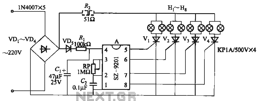
It utilizes the mains supply through a basic DC rectifier circuit. The circuit operates by converting alternating current (AC) from the mains supply into direct current (DC) using a rectifier. A typical implementation involves a bridge rectifier configuration, which consists...
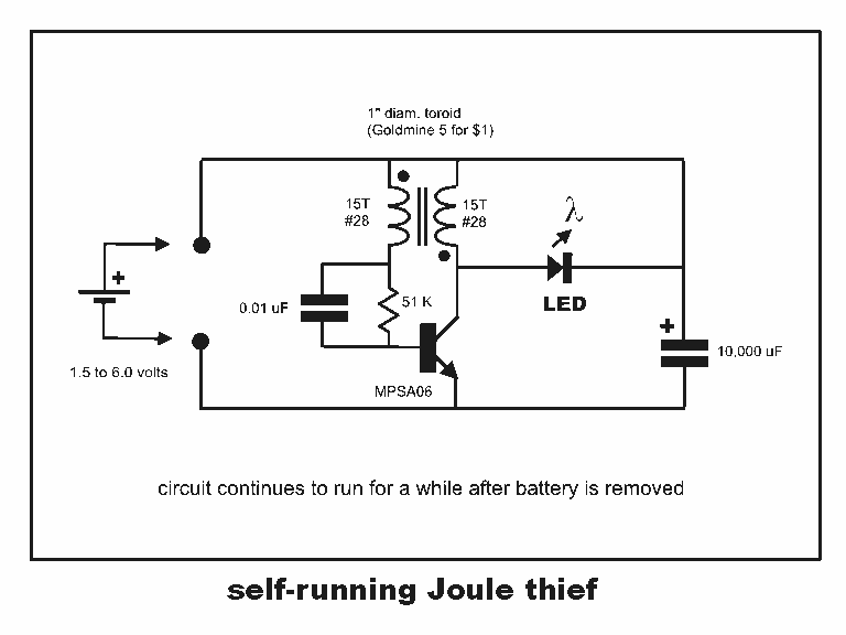
Professor Steven E. Jones' circuit demonstrates an 8x overunity. The concept of overunity refers to a system that produces more energy than is consumed, effectively achieving a coefficient of performance greater than one. In the context of Professor Steven E....
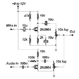
This two-channel audio mixer utilizes 2N3904 transistors to create two preamplifiers. The first preamplifier is designed for high gain, suitable for microphone input, while the second preamplifier allows for control over the audio level input. The audio mixer requires...
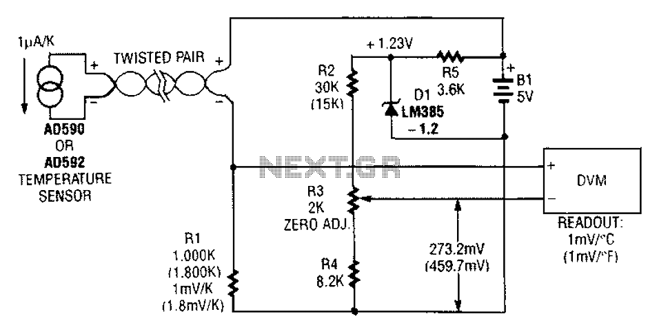
An AD590 or AD592 can be utilized in a transmission line for temperature data transmission. The circuit generates a value of 1 mV per degree Fahrenheit. The AD590 and AD592 are precision temperature sensors that output a voltage proportional to...
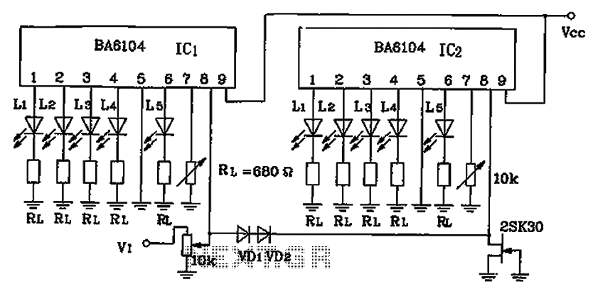
BA6104 is a five-digit LED level meter that functions as an LED display driver integrated circuit (IC). The configuration of the circuit is illustrated in the accompanying figure. The circuit utilizes a 10 by two-dot LED level display. The...
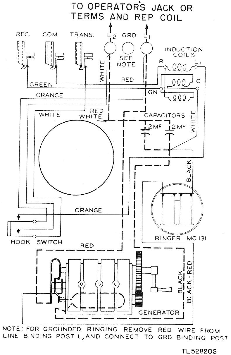
The EE-91 is a wall-mounted metal telephone box. It is a common battery phone, meaning the transmitter current is sourced from the central office battery. It features a single gong ringer and is equipped with a hand generator for...