
Color Sensor circuit
The colour sensor circuit is designed to detect and differentiate between eight distinct colours, leveraging both optical principles and digital electronics. The core components of the circuit include three Light Dependent Resistors (LDRs), which are sensitive to light intensity, and three convex lenses that focus light onto the LDRs. Each LDR is equipped with a corresponding colour filter: blue, green, and red. These filters are critical as they selectively allow specific wavelengths of light to pass through, corresponding to the primary colours.
When an object is placed in front of the sensor, the light reflected from the object enters the system through the lenses, which enhance the light intensity reaching the LDRs. The colour filters ensure that only the light of the corresponding primary colour can activate its respective LDR. In the case of secondary colours, two primary colour filters will allow the mixed light to pass through, resulting in two LDRs being triggered.
The logic processing is facilitated by a combination of AND and NOT gates. The output from the LDRs is converted into digital signals, where a logic '1' indicates a triggered state. The configuration allows for the identification of both primary and secondary colours based on which LDRs are activated. If all LDRs are triggered, the output indicates white, while if none are triggered, it indicates black.
To ensure accurate readings, the circuit incorporates adjustable potentiometers (VR1, VR2, VR3) that fine-tune the sensitivity of the LDRs to varying light conditions. The common terminals of the LDRs should be connected to a positive voltage supply to operate correctly. The LDRs should be housed in tubes with lenses positioned to direct light from the object, and the filters must be of high quality to prevent light distortion.
Proper assembly and calibration of the components are essential for optimal performance of the colour sensor. The effectiveness of the sensor is highly dependent on the precise alignment and quality of the optical components, as well as the ambient lighting conditions during operation.Colour sensor is an interesting project for hobbyists. The cir- cuit can sense eight colours, i.e. blue, green and red (primary colours); magenta, yellow and cyan (secondary colours); and black and white. The circuit is based on the fundamentals of optics and digital electronics. The object whose colour is required to be detected should be placed in front of the system. The light rays reflected from the object will fall on the three convex lenses which are fixed in front of the three LDRs.
The convex lenses are used to converge light rays. This helps to increase the sensitivity of LDRs. Blue, green and red glass plates (filters) are fixed in front of LDR1, LDR2 and LDR3 respectively. When reflected light rays from the object fall on the gadget, the coloured filter glass plates determine which of the LDRs would get triggered. The circuit makes use of only ?AND? gates and ?NOT? gates. When a primary coloured light ray falls on the system, the glass plate corresponding to that primary colour will allow that specific light to pass through. But the other two glass plates will not allow any light to pass through. Thus only one LDR will get triggered and the gate output corresponding to that LDR will become logic 1 to indicate which colour it is.
Similarly, when a secondary coloured light ray falls on the system, the two primary glass plates corres- ponding to the mixed colour will allow that light to pass through while the remaining one will not allow any light ray to pass through it. As a result two of the LDRs get triggered and the gate output corresponding to these will become logic 1 and indicate which colour it is.
When all the LDRs get triggered or remain untriggered, you will observe white and black light indications respectively. Following points may be carefully noted : 1. Potmeters VR1, VR2 and VR3 may be used to adjust the sensitivity of the LDRs. 2. Common ends of the LDRs should be connected to positive supply. 3. Use good quality light filters. The LDR is mounded in a tube, behind a lens, and aimed at the object. The coloured glass filter should be fixed in front of the LDR as shown in the figure. Make three of that kind and fix them in a suitable case. Adjustments are critical and the gadget performance would depend upon its proper fabrication and use of correct filters as well as light conditions.
🔗 External reference
Related Circuits
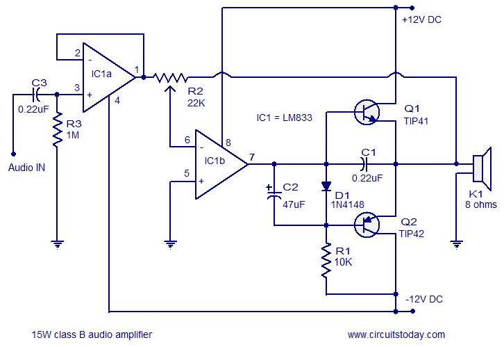
A 15 Watts Class B audio amplifier circuit is designed using a dual op-amp LM833. The schematic diagram is provided, and a potentiometer allows for volume control. The 15 Watts Class B audio amplifier circuit utilizes the LM833 dual operational...
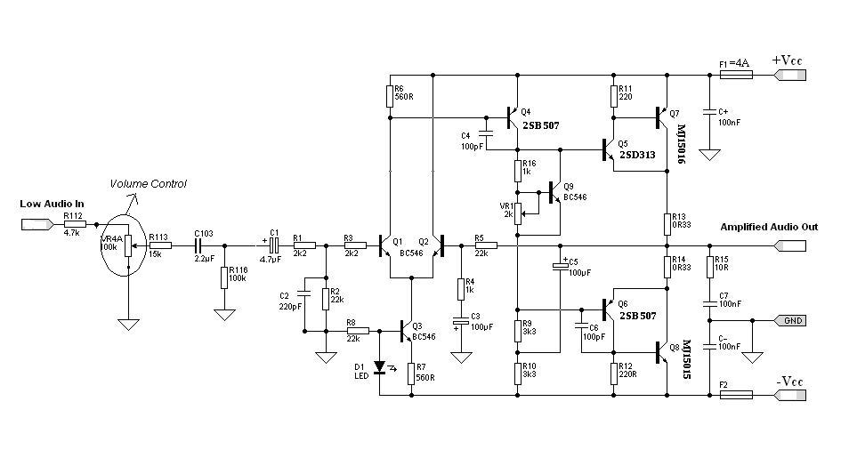
Designing an audio amplifier from scratch using discrete components is an engaging task, as it enables users to create amplifiers that meet diverse requirements. Audio amplifiers can enhance low-level sounds from mobile devices, making them louder and more vibrant....
The schematic represents a water level alarm circuit. This circuit functions as a water level sensor and emits a melodious alarm sound when the two probes within the circuit detect the presence of water. This water level indicator circuit...
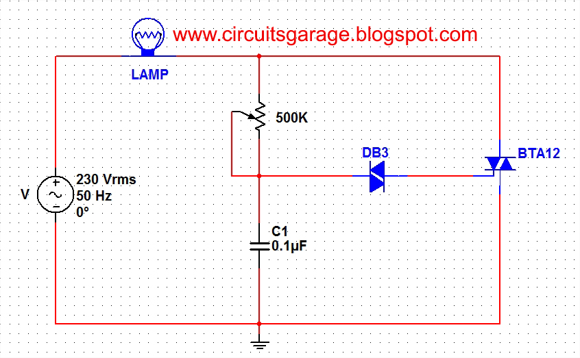
A light dimmer circuit is used to adjust the illumination of a lamp. The following circuit illustrates a basic TRIAC triggering circuit that utilizes a DIAC. In this circuit, the illumination of the light is regulated through the interaction...
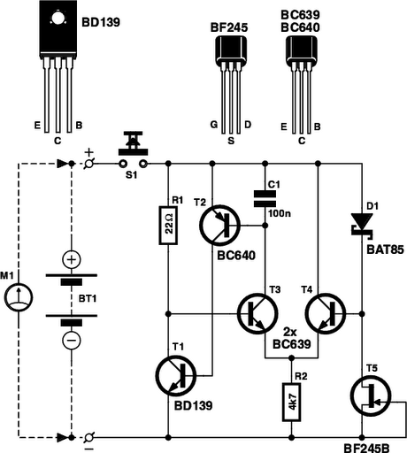
Is the battery empty, or is there something wrong with the device? This question can be challenging when a battery-powered device, such as a Walkman, appears to be non-functional upon switching it on. Before seeking professional servicing, the initial...
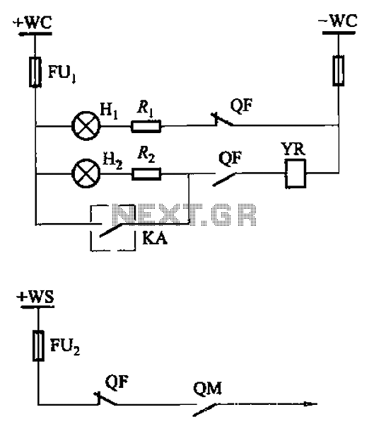
The CS2 type is a manually operated breaker mechanism commonly utilized for AC power operation and manual control signal circuits, as depicted in Figure 6-68. The circuit includes various components: wc for small signal bus control, QF for auxiliary...