
Hi-Fi Tone Control

The 20-band stereo graphic equalizer circuit functions by allowing precise adjustments to the audio signal across a wide range of frequencies, enhancing the listening experience by tailoring sound to user preferences. Each band in the equalizer corresponds to a specific frequency range, and the circuit employs a series of filters to isolate these frequencies. The use of high-quality components is crucial in maintaining signal integrity and minimizing noise, which can adversely affect audio quality.
The 12V stereo tone control circuit serves a similar purpose but focuses on broader tonal adjustments, utilizing transistors for signal amplification and control. The inclusion of the LM1036 IC in the stereo audio tone control circuit allows for sophisticated manipulation of sound, providing users with the ability to finely tune bass, treble, and volume levels, as well as balance the audio output between channels. This versatility makes it suitable for a variety of audio applications, ensuring compatibility with numerous devices.
The ACTOR Active Tone Control circuit enhances audio signals through an active approach, employing feedback mechanisms to achieve greater control over sound characteristics. This circuit's design is particularly beneficial for users seeking to boost specific audio frequencies dynamically.
The FM transmitter circuit is notable for its ability to transmit audio signals wirelessly, making it a valuable component for audio systems that require flexibility in signal distribution. Its compact design and low power requirements make it ideal for portable applications, while the specified range ensures adequate coverage for most environments.
Finally, the adjustable power supply circuit is essential for powering various electronic projects, providing users with the flexibility to customize voltage and current outputs according to their specific needs. This feature is particularly useful in experimental setups and for powering sensitive components that require precise voltage levels.The following diagram is the circuit diagram of 20 band stereo graphic equaliser which will controlling the audio signal in specific frequency range. This circuit must be connected before the amplifier circuit. For maximum performance, you may use high quality electronic component such as metalfilm resistor, MKM capacitor (nonpolar), tantalum capa
citor (bipolar). You may replace. The following diagram is the circuit diagram of 12V stereo tone control which also available in kit, you may find the kit at electronic part store around your place. The circuit build based on ordinary tone control circuit, using 2 transistors FCS9014 in each channel, so there are will be 4 transistors in this 12v.
This is a stereo audio tone control circuit which build based on IC LM1036. This circuit will controll bass/treble level tone, volume and balance between right channel and left channel (input 1 and 2 ). You may use this circuit for stereo applications such as car radio, TV and audio systems, mp3 player, dvd player, .
The following diagram is the schematic diagram of Active Tone Control circuit, or we often call thic circuit as "ACTOR" Active Tone Control or ACTOR is a electronic audio circuit that serves to increase the Loudness (Bass and Treble audio signal) is active because it uses the Baxandall system. This circuit does not use a. This the Good Quality FM transmitter for your stereo or any other amplifier gives you a pretty good signal strength up to a range of 500 metres having a power output of about 200 mW.
This circuit can be operated with a 9V battery. The audio-frequency modulation stage is constructed close to transistor BF494 (T1), . This is high quality stabilized power supply circuit diagram. You will able to adjust the output voltage from 0 volt up to 30 volt DC. You also able to adjust the current output value from 0. 002 A to 3 A. Detail explanation include the PCB layout, visit this page 🔗 External reference
Related Circuits
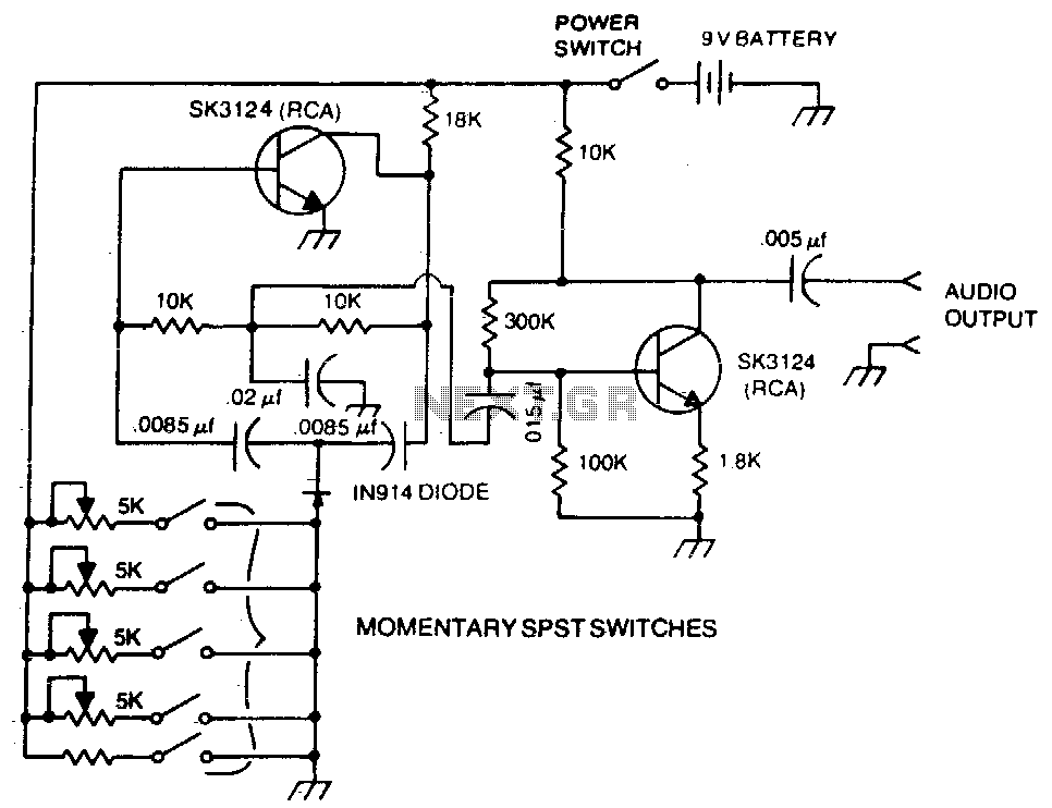
A basic twin-T circuit uses resistors to accurately set the frequency of the output tones, selected by pushbuttons. Momentary switches generate a tone only when the button is pressed. The twin-T oscillator circuit is a well-known electronic configuration used for...
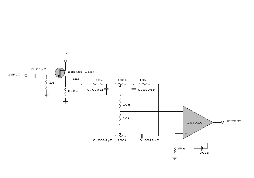
This circuit is a simple series tone control circuit. It utilizes the surgical amplifier LM301A. The JFET 2N3684 provides high input impedance and low noise for the unbuffered operational amplifier, which operates in an equalizer (EQ) configuration. Further details...
This small circuit is designed to verify the basic functionality of an infrared remote control unit. The circuit utilizes a straightforward approach by connecting a piezo buzzer directly to an IR receiver integrated circuit (IC). This configuration is as...
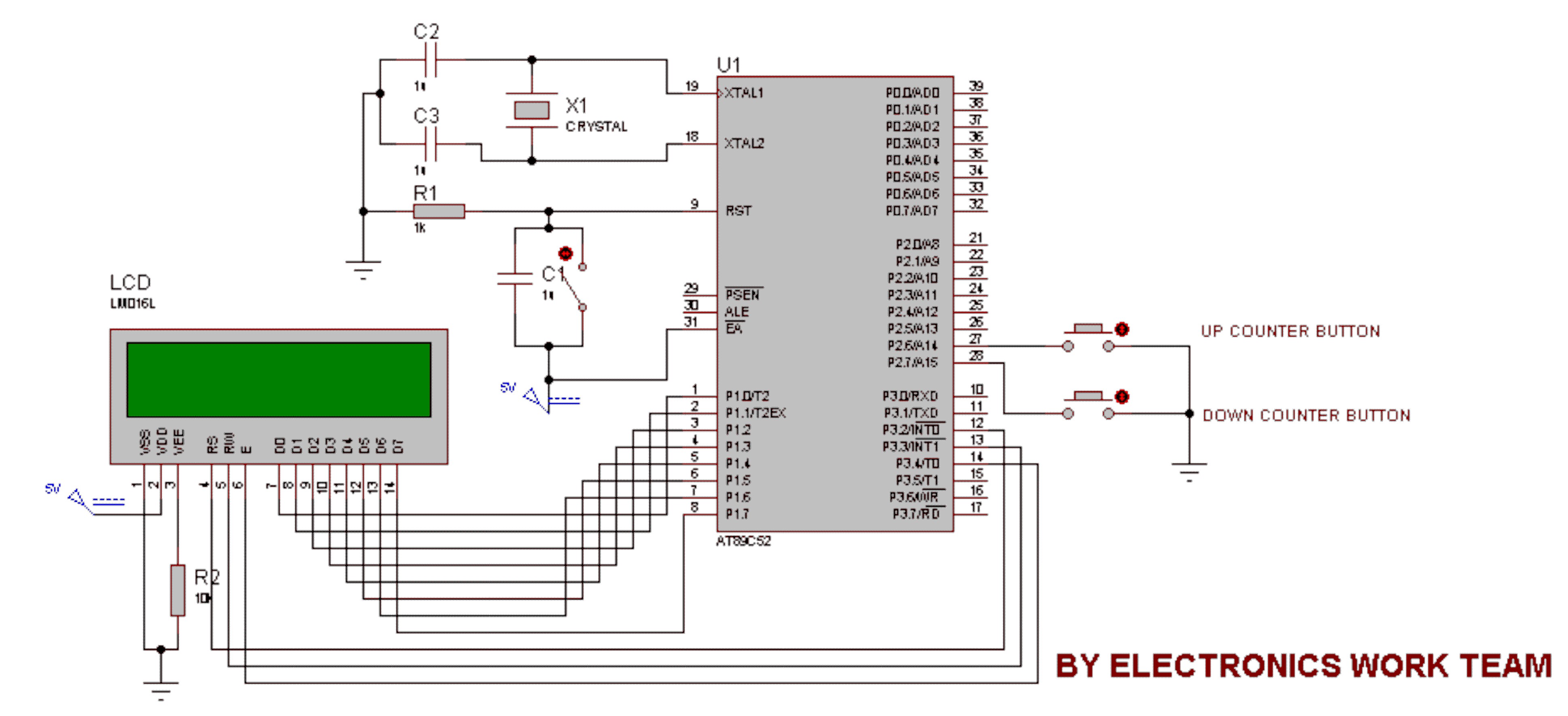
This circuit utilizes a 16x2 LCD to display a count value using an 8051 microcontroller. The maximum count value is set to 99. The circuit consists of the 8051 microcontroller, a 16x2 LCD, and two switches designated for incrementing...
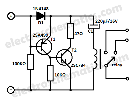
This low current relay circuit is designed for use in battery-operated electronic devices. Its operating current is in microamperes (µA). This is achieved by using a bistable relay and incorporating additional components to enable the relay to function like...
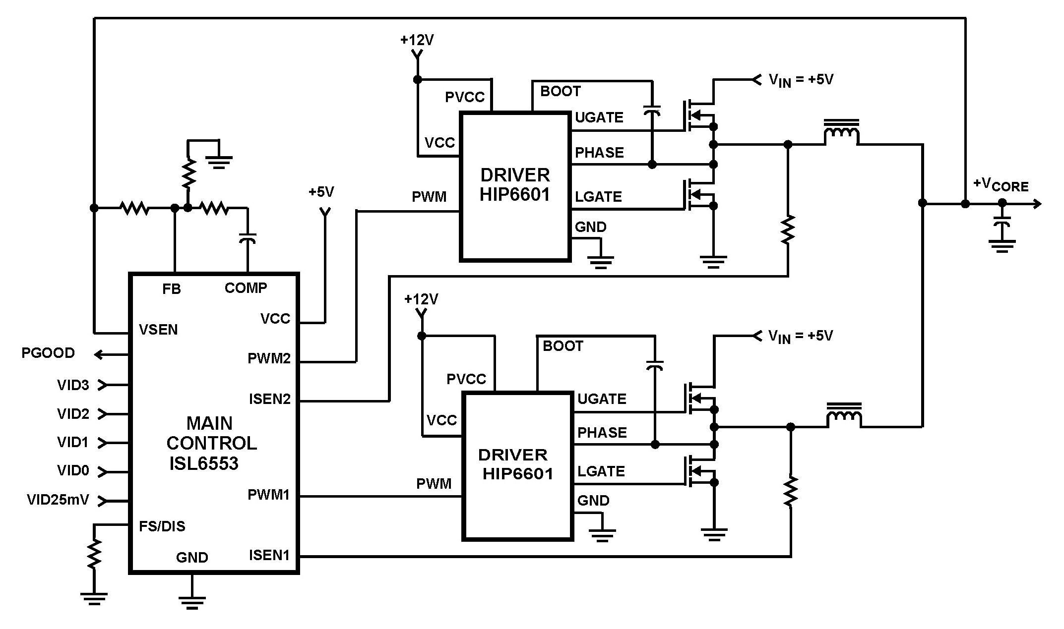
The ISL6553 multiphase PWM control IC, along with its associated gate drivers (HIP6601, HIP6602, or HIP6603), establishes a precise voltage regulation system tailored for advanced microprocessors. Multiphase power conversion represents a significant evolution from traditional single-phase converter configurations, addressing...