
Dispenser Aucma temperature detection control circuit
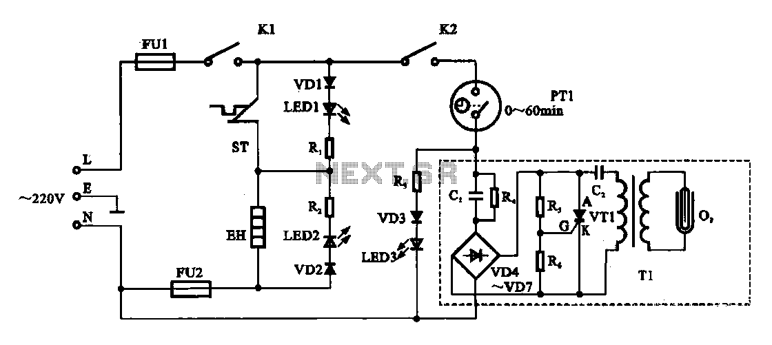
The AC 22V supply passes through a resistor (R4) and is rectified by a diode bridge (VD4 to VD7), converting it to nearly 30V DC for use in the oscillation circuit. The oscillation circuit includes a thyristor (VT1) and an oscillation capacitor (C2), along with a high-voltage transformer (Tl). Upon startup, the DC voltage from the bridge rectifier charges capacitor C2. As the voltage across C2 rises, it reaches a trigger voltage that activates the thyristor VT1, allowing C2 to discharge. This sudden drop in voltage at thyristor VT1's anode-cathode junction leads to a cut-off. The bridge rectifier then recharges, and the cycle repeats, causing the circuit to oscillate. The secondary output of the high-voltage transformer (Tl) powers the ozone tube (03), which generates ozone for disinfecting the food storage cabinet.
An indicator is included to display the operational status of the fresh cabinet. When the power switch and door switch are closed, and the timer is set (PT1), the ozone generator activates, lighting the fresh indicator (LED3). If the timer reaches zero or if the door switch is opened during the preservation process, the circuit disconnects, halting the ozone generator and extinguishing the fresh indicator light.
The circuit design incorporates essential components like fuses for safety, switches for user interaction, and timers for operational control, ensuring effective temperature detection and ozone generation for food preservation. The use of oscillation circuits and thyristors allows for efficient high-voltage generation, critical for the ozone production process. Overall, this schematic provides a robust solution for maintaining food freshness through effective temperature control and disinfection.Dispenser (Aucma) temperature detection control circuit It shows the dispenser (Aucma) temperature detection control circuit. The dispenser is composed of two parts, one part i s heating control circuit: another part of the fresh cabinet control circuit is to provide ozone generator power supply, storage cabinets for food inside the deodorant, play a role in preservation. AC 22V power supply from the K L (live) side by fuses FU1, power switch], door switch K2, the timer PT1 to smell oxygen generator circuitry.
AC 22V through R4, after CI anti-shock circuit consists VD4 ~ VD7 diode bridge rectifier circuit bridge rectifier is formed nearly 30V dc voltage of the rectifier to the oscillation circuit. Oscillation circuit is a thyristor VT1, and the oscillation capacitor c2 with high voltage transformers and other parts of the Tl.
Boot, bridge rectifier output DC voltage begins to charge the capacitor c2, c2 on the electric pressure, and at the same time R5 dividing point (trigger thyristor VT terminal G) of the voltage rise, when rising voltage reaches a trigger voltage when the charge thyristor VT1 conduction, the capacitor C2 is let go, the AK voltage thyristor VT1 between suddenly lowered the cut-off. Next to the bridge rectifier circuit again cz charge, G terminal voltage thyristor TV1 rises again, again through the thyristor VT1 conduction discharge.
Continually repeating this process of charging and discharging, the circuit will oscillate, so high-voltage transformer Tl secondary oscillating high pressure to obtain ozone tube 03 power supply, ozone tube 03 to produce ozone work in food storage cabinets tough disinfection. Preservation indicator is used to display the working status of fresh cabinet, when the power switch K], the door switch K2 are in a closed state, the opening set timer PT1, set the preservation time, when the ozone generator started working, fresh indicator LED3 is lit; when the timer PT1 time to zero, or opened the door switch in the preservation process, and preservation of the circuit will be disconnected, the ozone generator stops working, fresh light is also extinguished
Related Circuits
This diagram illustrates the usage of the L200 device for controlling the speed of permanent magnet motors. By utilizing resistors R1 and R2, the desired speed can be achieved. The L200 is a versatile integrated circuit designed for various applications,...
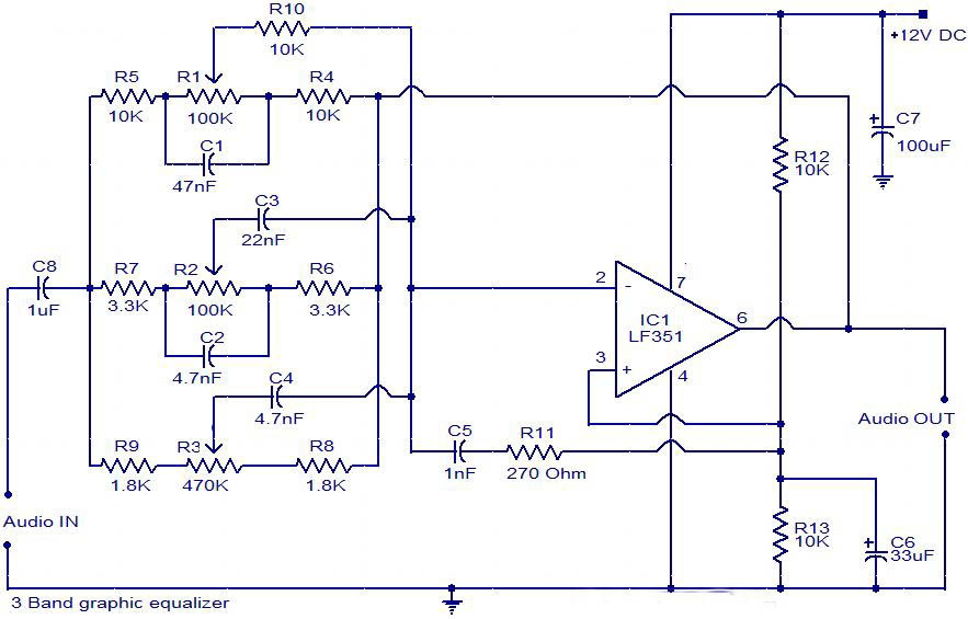
The circuit is a diagram of a simple three-band graphic equalizer circuit. An IC known as the LF351 is utilized in this design. The three-band graphic equalizer circuit is designed to adjust the amplitude of audio signals across three distinct...
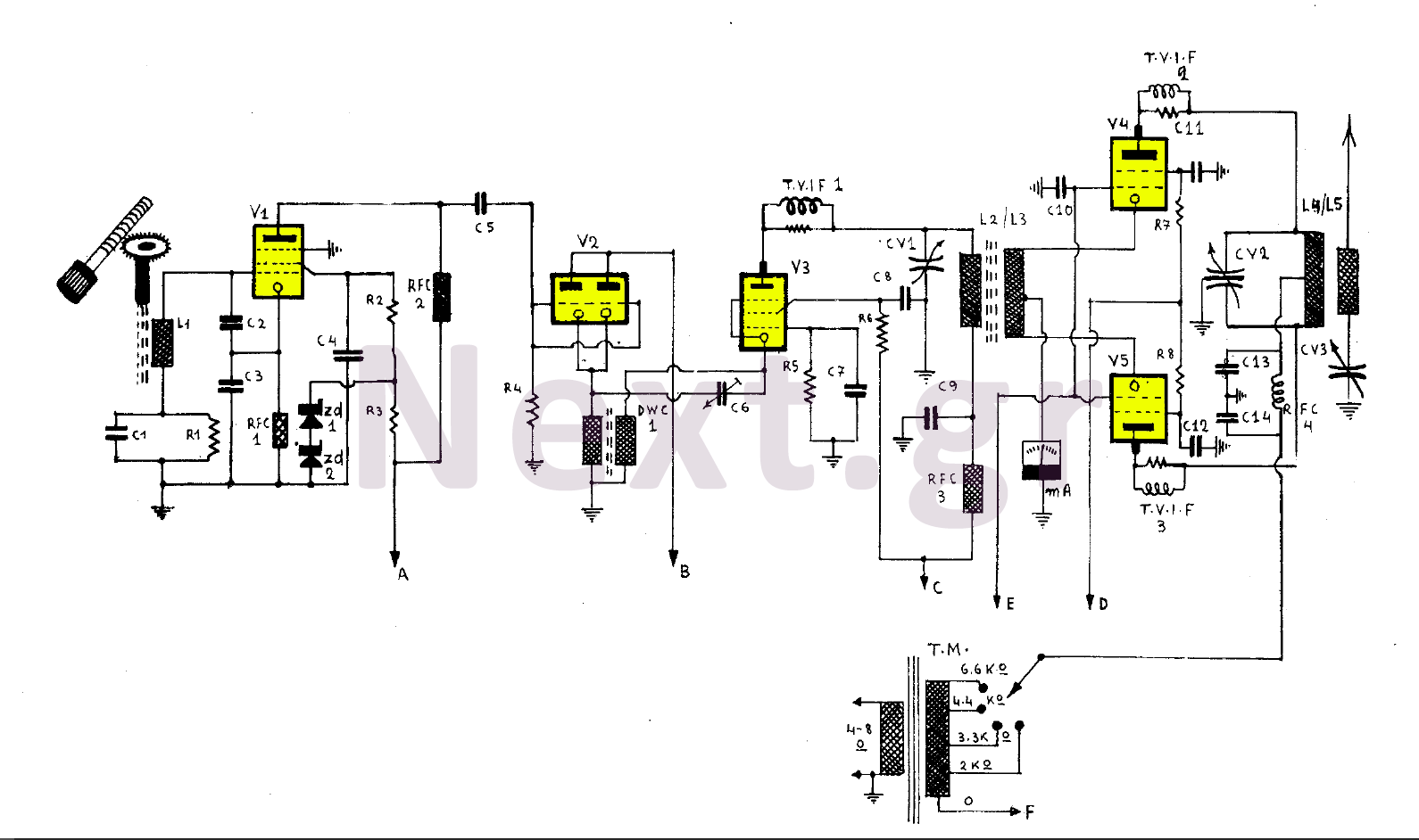
This 255W transmitter operates using coils designed for both medium and short waves. The antenna power is set at 255W and includes four operational states. The first state utilizes an EF80 tube functioning as a Colpitts Clapp oscillator. Frequency...

A Countdown Timer Circuit is a project submitted by a group of students for their ECE 130 - Computer Application class on August 31, 2006, at the University of St. La Salle, Philippines. The seven-segment decoder is utilized in...
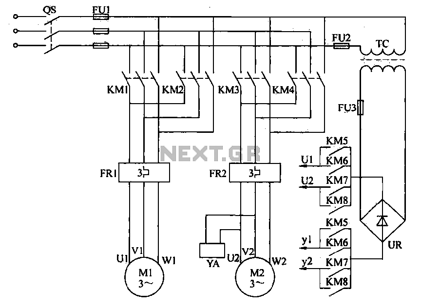
Electric driving is essential for modernizing plant material transport. Traditional control methods are primarily semi-manually operated automatic systems. To enhance efficiency, promote production automation, and reduce labor intensity, electrical automation for material transport is often implemented. This automation allows...
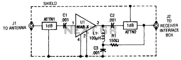
The MAR-x preamplifier is designed to operate within a frequency range of up to 1.5 or 2 GHz, depending on the selected MAR-x integrated circuit (IC). For applications requiring a low noise figure, ATTN1 should be omitted. Both ATTN1...
Warning: include(partials/cookie-banner.php): Failed to open stream: Permission denied in /var/www/html/nextgr/view-circuit.php on line 713
Warning: include(): Failed opening 'partials/cookie-banner.php' for inclusion (include_path='.:/usr/share/php') in /var/www/html/nextgr/view-circuit.php on line 713