
Simple Graphic Equalizer Circuit
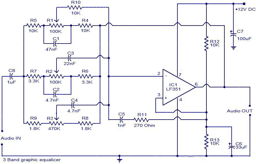
The three-band graphic equalizer circuit is designed to adjust the amplitude of audio signals across three distinct frequency bands: bass, midrange, and treble. The LF351 operational amplifier is a key component in this circuit, providing the necessary gain and filtering capabilities.
The circuit typically consists of three separate band-pass filter sections, each tailored to a specific frequency range. The first section addresses the low frequencies (bass), the second targets the mid frequencies, and the third focuses on high frequencies (treble). Each section utilizes resistors and capacitors to set the center frequency and bandwidth, allowing for precise control over the audio signal.
The LF351 IC, being a low-noise, high-speed operational amplifier, is well-suited for audio applications. It is configured in a non-inverting amplifier configuration for each band, ensuring that the output signal maintains the same phase as the input while allowing for gain adjustments through feedback resistors.
The output of each band is then combined, often through a summing amplifier configuration, to produce a final output signal that reflects the adjusted frequency response based on the user’s settings. Controls such as potentiometers may be employed in each band to allow users to increase or decrease the gain for each frequency range, providing a customizable audio experience.
Power supply considerations for the LF351 should also be noted. The IC typically requires a dual power supply, often +15V and -15V, to function properly, ensuring that the output can swing above and below ground.
In summary, the simple three-band graphic equalizer circuit employing the LF351 IC is an effective tool for audio signal processing, allowing for enhanced control over sound characteristics across various frequency bands.The Circuit is the diagram of a simple three band graphic equalizer circuit. An IC called LF 351 IC is used here. 🔗 External reference
Related Circuits
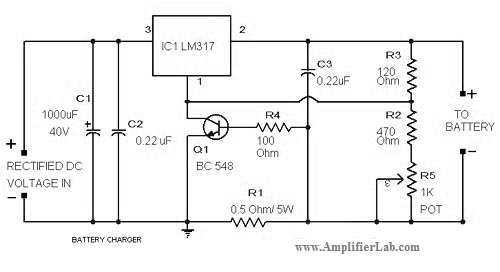
The circuit diagram of a lead-acid battery charger is presented here. The main component of this circuit is the IC LM317. The lead-acid battery charger circuit utilizing the LM317 voltage regulator is designed to efficiently charge lead-acid batteries while providing...
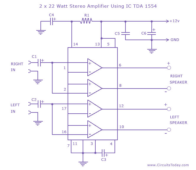
A high-quality stereo amplifier circuit of 44 Watts (22 Watts per channel) using the TDA 1554 IC. This is a powerful audio amplifier circuit for 2 channels. The described stereo amplifier circuit utilizes the TDA 1554 integrated circuit (IC), which...
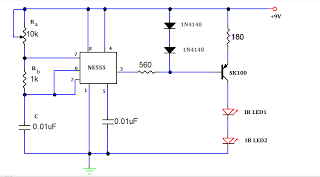
A TV remote jammer circuit using the NE555 timer IC. This device allows users to watch their favorite TV channels without interruptions, as it prevents others from changing the channel using a remote control when the circuit is activated....

This is a design circuit for a UHF transmitter. The TV transmitter operates within the UHF frequency range of 470-580 MHz, specifically on channels 21-34. It can transmit signals over distances of 30-100 meters using a cable length of...
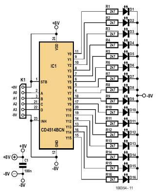
The indicator described here is specifically designed for adjusting the dynamic limiter outlined elsewhere in this edition and checking if the maximum level of the reference voltage (P1) requires modification. A 4-to-16 decoder integrated circuit (IC) of type 4514...

This is a circuit design for an FSK demodulator, which is an electronic device that converts an FSK signal into a serial digital signal. FSK modulation is used to transmit digital serial data, and demodulation is necessary to retrieve...