
0 to 9 asynchronous decade counter 7490 display
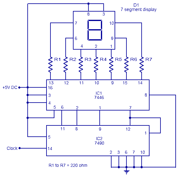
The circuit utilizes the 7490 asynchronous decade counter, which is capable of counting from 0 to 9 in binary-coded decimal (BCD) format. The output pins of IC2 correspond to the BCD representation of the decimal digits. This output is fed into the 7446 decoder/driver (IC1), which translates the BCD signals into the appropriate signals required to illuminate the segments of the seven-segment display (D1).
The seven-segment display consists of seven individual LEDs, each labeled from 'a' to 'g', which represent the segments that can be illuminated to form the digits 0 through 9. In this particular configuration, a common anode type display is employed, meaning that all the anodes of the LEDs are connected together to a positive voltage supply, while the individual cathodes are connected to the output pins of the decoder. This configuration requires that the outputs of the 7446 be driven low to turn on the respective segments of the display.
To ensure proper operation and to prevent excessive current from flowing through the LEDs, current-limiting resistors (R1 to R7) are placed in series with each segment of the display. These resistors are calculated based on the supply voltage, the forward voltage drop of the LEDs, and the desired forward current to ensure longevity and reliability of the display.
The operation of the circuit is straightforward. Upon receiving a clock pulse, the 7490 counter increments its count, changing its BCD output. Each time this occurs, the 7446 decoder interprets the new BCD value and activates the corresponding segments of the display to show the appropriate digit. This allows for a visual representation of the count, making the circuit suitable for applications such as digital counters, timers, or frequency displays.The circuit is based on asynchronous decade counter 7490(IC2), a 7 segment display (D1), and a seven segment decoder/driver IC 7446 (IC1).The seven segment display consists of 7 LEDs labelled a through g. By forward biasing different LEDs, we can display the digits 0 through 9. Seven segment displays are of two types, common cathode and common anode. In common anode type anodes of all the seven LEDs are tied together, while in common cathode type all cathodes are tied together. The seven segment display used here is a common anode type .Resistor R1 to R7 are current limiting resistors.
IC 7446 is a decoder/driver IC used to drive the seven segment display. Working of this circuit is very simple. For every clock pulse the BCD output of the IC2 (7490) will advance by one bit. The IC1 (7446) will decode this BCD output to corresponding the seven segment form and will drive the display to indicate the corresponding digit. Email ThisBlogThis!Share to TwitterShare to FacebookShare to Google Buzz 🔗 External reference
Related Circuits
The number of pulses at the input can be visually confirmed by connecting a light-emitting diode to the output of the counter. In this circuit, a counter is utilized to count the number of input pulses. The output of the...
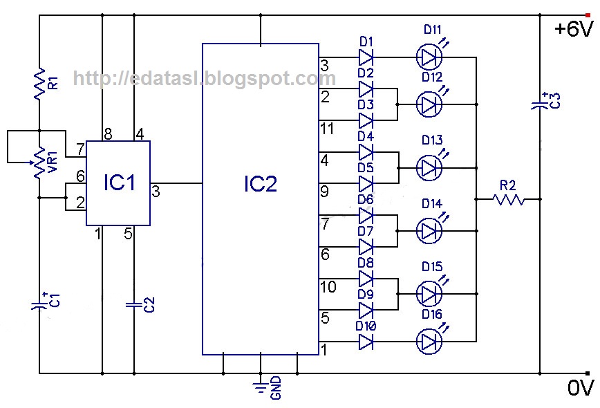
At the onset of the second clock cycle, the output labeled "0" transitions to a LOW state while the output labeled "1" transitions to a HIGH state. This sequence persists across ten outputs, eventually cycling back to output "0"...
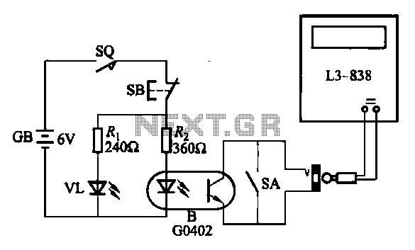
An electronic calculator features an automatic counting interface circuit, as illustrated in the accompanying figures. Figure (a) depicts a stroke switch controlled via optocoupler B. Figure (b) shows the application of a reed switch (KR) for pulse control signals....
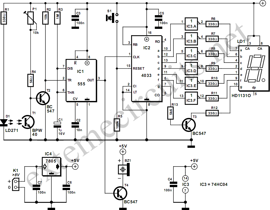
The described circuit counts the number of interruptions of an infrared beam. This could be used to tally the number of people entering a room or to monitor how often an object, such as a ball, passes through an...
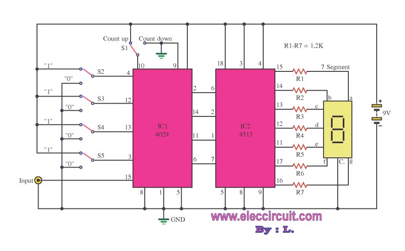
This is a simple digital counter circuit utilizing the IC 4029 to process binary data, which is then sent to the IC 4513, a driver IC for a 7-segment display to show the output. The digital counter circuit is designed...
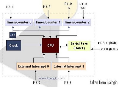
The diagram below illustrates a simplified representation of the main peripherals present in the 89S52 microcontroller, which is part of the 8052/8051 family. The 89S52 includes three Timers/Counters. The term "Timer/Counter" is applicable because this unit can function either...
Warning: include(partials/cookie-banner.php): Failed to open stream: Permission denied in /var/www/html/nextgr/view-circuit.php on line 713
Warning: include(): Failed opening 'partials/cookie-banner.php' for inclusion (include_path='.:/usr/share/php') in /var/www/html/nextgr/view-circuit.php on line 713