
DIY Arduino Powered Diversity

The Arduino-powered diversity controller is designed to enhance signal reception by selecting the strongest video feed from multiple sources. The controller's architecture includes a microcontroller unit (MCU) that processes the RSSI values from the two video receivers. These receivers are typically connected to antennas that capture video signals. The RSSI readings are essential as they provide real-time feedback on the strength of the received signals.
The MAX4618 video switch IC is a crucial component in this design, allowing for seamless switching between the video inputs based on the RSSI values. This IC is designed for low distortion and high-speed switching, making it suitable for video applications. The controller can be configured to select the input with the highest RSSI value, ensuring the best possible video quality.
In terms of hardware configuration, the two video receivers should be connected to the Arduino's analog input pins to read the RSSI values. The outputs from the MAX4618 will be connected to the amplified outputs, allowing for the final video signal to be sent to a display or further processing unit. The design can be expanded to support additional inputs by utilizing the extra capacity of the hardware, which can handle up to four inputs.
The different behaviors of the RSSI outputs from the two receivers indicate a need for calibration within the software. The Arduino code should account for these variations, allowing the MCU to interpret the RSSI values correctly and switch between inputs accordingly. Proper filtering and averaging techniques can be implemented to stabilize the readings and prevent rapid switching between inputs due to minor fluctuations in signal strength.
Overall, this Arduino-powered diversity controller represents a robust solution for applications requiring reliable video signal reception, particularly in environments where signal strength may vary significantly. The combination of the Arduino platform, the MAX4618 IC, and the RSSI feedback mechanism provides a versatile and effective approach to managing multiple video inputs.I finally got all of the materials I needed in to work on my arduino powered Diversity controller. The plan is to support 2 inputs (though the hardware can support up to 4 inputs), and 4 amplified outputs. The diversity will use RSSI to compare feeds and I am using a MAX4618 as the video switch IC. I already broke out the RSSI pin on both of my video receivers, and oddly enough one of them the voltage goes up as signal improves, and on the other it goes downward as it improves!
Sofar I.. 🔗 External reference
Related Circuits
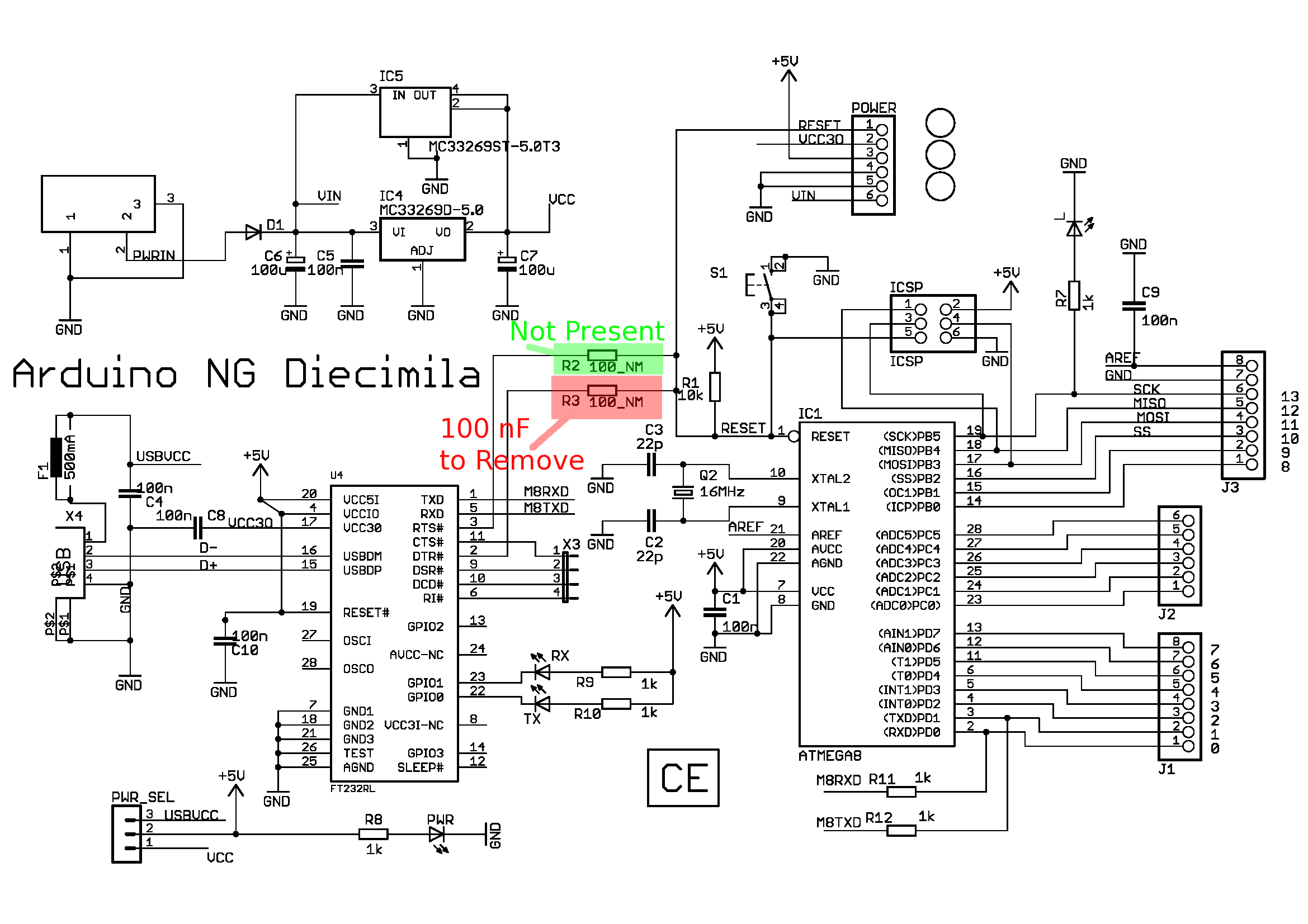
This article discusses the Diecimila; however, there is a newer article that focuses on the Duemilanove. A shift in topic is presented, providing instructions on how to modify an Arduino board to enable useful functions such as debugging. The...
The core component of this DIY metal detector circuit is the CS209A integrated circuit (IC). The metal detector is constructed using a single 100µH coil, which has a diameter of 40 mm. The CS209A IC serves as the primary signal...
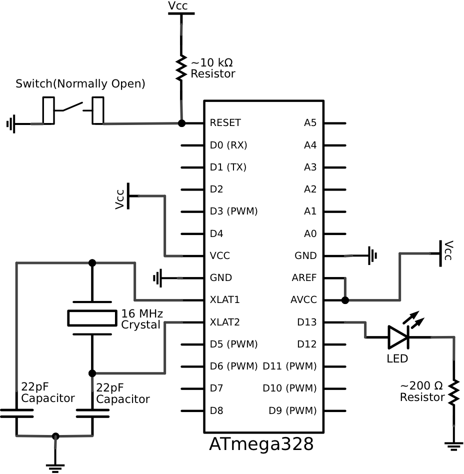
This schematic represents a minimalistic circuit that includes only the essential components required for operating an ATmega328 microcontroller with the Arduino Uno bootloader. The design of the voltage regulation circuit is left to the user. Connections to AREF and...
This circuit performs a rapid battery test without requiring an external power supply or costly moving-coil voltmeters. It features two ranges: when switch SW1 is set as indicated in the circuit diagram, the device can test batteries ranging from...
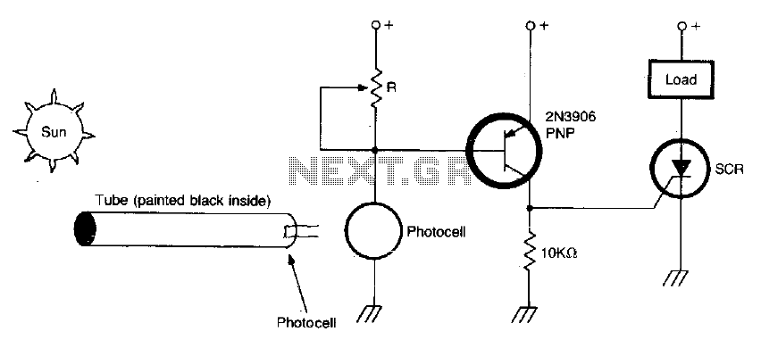
The circuit activates when light, specifically sunlight, strikes the photocell. A potentiometer, labeled R, adjusts the light level at which the alarm is triggered. Additionally, a painted tube, with a black interior, can be utilized on the photocell to...
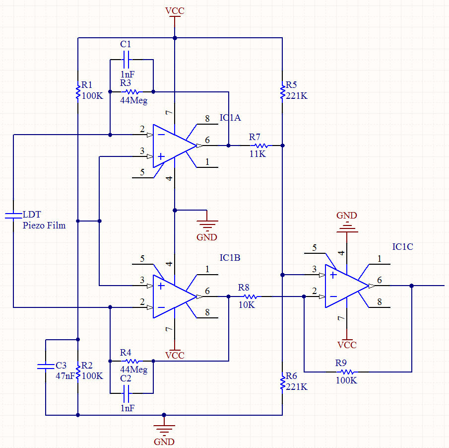
To reduce the resonant frequency and obtain useful signals, washers were placed on a bolt along with nuts for experimentation. An oscilloscope with FFT was utilized to adjust the weight at the tip of the film until frequencies around...