
Radio Amplifiers Circuits

This FM amplifier circuit operates within the specified frequency range of 88 to 108 MHz, making it suitable for standard FM radio applications. The design utilizes high-performance components, including the DV28120T V-MOSFET transistors, which are known for their efficiency and reliability in RF amplification. The push-pull configuration enhances linearity and minimizes distortion, resulting in high-fidelity audio output.
The coil specifications are critical for achieving optimal performance. The use of RG142 coaxial cable for winding the coils ensures low loss and high-quality signal transmission. The dimensions and construction of the coils, with tightly wound turns and no gaps, are essential for maintaining the desired inductance and ensuring effective RF performance.
In addition to the 1W amplifier, the circuit can be scaled for higher power outputs, such as the 200W capability in the 144 MHz band, by using multiple DV28120T transistors in a push-pull arrangement. This scalability allows for versatility in applications ranging from low-power personal transmitters to higher-power broadcast systems.
The integration of the VN66AF transistor in the 27 MHz amplifier highlights the importance of selecting components that provide high gain and affordability. This transistor's characteristics make it a suitable choice for low-power applications, further demonstrating the circuit's adaptability.
The BLF 245 transistor is another key component, known for its robustness in high-power applications. The ability to use a processor heatsink and cooler ensures that the amplifier operates within safe thermal limits, crucial for maintaining performance and longevity.
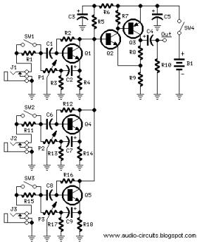
Lastly, the inclusion of the MRF 171A MOSFET in the wideband FM power amplifier circuit exemplifies the design's capability to handle varying input power levels while delivering significant output power. With a gain of 20 dB, this amplifier can effectively boost weaker signals, making it suitable for a variety of RF applications. Overall, the described FM amplifier circuits are versatile, efficient, and capable of delivering high-quality RF amplification across multiple frequency bands.This is a 1 watt fm amplifier with a good design that can be used to amplify a rf signal in the 88 108 MHz band. It is very sensitive if you use good rf power amplifier transistors, trimmers and coils. It has a power amplification factor of 9 to 12 dB (9 to 15 times). At an input power of 0. 1W the output will be 1W. This is a 2 meters 144 Mhz rf amplifier wich works in push pull and is build with DV28120T Vmos. You can use coils made form RG142 coaxial cable or similar, 620mm long, 5mm diameter, 6 turns with inside diameter 30mm no gaps between. VMOS RF amplifier circuit. 2 meters 144MHz push pull amplifier wich can generate 200W, how does it sound Sounds delicious with 2 DV28120T transistors.
DV28120T push pull amplifier circuit. The 10 meters 27MHz CW radio amplifier is equiped with VN66AF transistor produced by Siliconix wich has some advantages: its cheap, great dielectric insulation and high gain. Here we use VN66AF as an rf amplifier for 10m band (26 30 MHz ). With this 27MHz rf amplifier, small transmitters ~ 200mW, can be transformed in. This fm 88-108 Mhz radio amplifier is equiped with BLF 245 and can be user with a heatsink from a processor and cooler.
The BLF 245 Datasheet can be downloaded over here -> blf245-datasheet BLF245 amplifier circuit. One wideband fm power amplifier designed with MRF 171A MosFet transistor. The output rf power is somewhere around 40W, the gains is 20dB ( 100 X ). The input rf power is. 🔗 External reference
Related Circuits
The following circuit illustrates a Mini Audio Mixer with Level Control Circuits. Features include switchable high/low sensitivity, providing high performance. The Mini Audio Mixer circuit is designed to facilitate the mixing of multiple audio signals while allowing for level control...
Many antique radios operate on batteries, including tube portables like the Zenith model K-401 and "farm" radios used in rural areas without electrical power. This article provides historical context on battery usage in early radios and offers guidance on...
The EDFET drives like a FET, but with the bias stability of bipolar. Amps of output current can be controlled by milliamps of input current. The current gain is a design choice dictated by bandwidth. Two of things you...
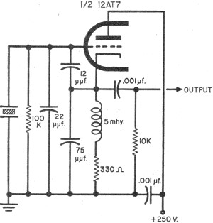
To update the fundamental oscillator circuits, simply replace the transistors with tubes. Alternatively, if one owns a vintage vacuum tube radio, it may be of interest to learn about historical practices. In general, the foundational principles of electronic circuits...
The only drawback of a single operational amplifier (op-amp) stage is that it inverts the signal, necessitating an additional inverting buffer to restore the original phase if absolute phase is a concern. Various schematics exist for both configurations, but...
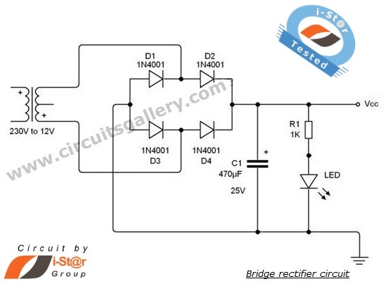
A rectifier is an electronic circuit that converts AC voltage to DC voltage. It can be implemented using a combination of capacitors and diodes. The unique property of diodes, which allows current to flow in a single direction, is...