
arduino scr

The circuit utilizes specific pin definitions for control and input, including triac_control (pin 5), powerIndicator (pin 12), sensorPin (pin 0), irq_Pin (pin 2), and powerOn (pin 4). A volatile byte flag_bit1 is declared to manage the interrupt request (IRQ) flag, while an integer variable analogValue is initialized to store the analog reading from the sensor. The setup function configures the pin modes and initializes the digital states for the triac control and power indicator LEDs. The attachInterrupt function links the interrupt service routine to the specified pin, allowing for real-time response to the zero-crossing signal from the opto-coupler.
In the loop function, the state of the powerOn pin is monitored, and the power indicator LED is activated accordingly. If the flag_bit1 indicates an interrupt has occurred and the powerOn pin is low, the analog value from the sensor is read, and a delay is introduced based on this value to determine the SCR firing time. The triac is turned on and off with precise timing, allowing for effective control of the LED brightness. The flag is then cleared to prepare for the next interrupt. The flag1 function sets the interrupt flag, enabling the loop to respond to the next zero-crossing event.In this circuit we demonstrate how to use SCRs to control low-voltage pulsating DC to operate homemade LED light panels. While in this circuit I use the Arduino, the concepts should work with any number of micro-controllers using either hardware interrupts or polling.
We must use pulsating DC or the SCR won`t operate properly. See Basic SCRs/Triac s. In the main circuit diagram above transformer T1, D1, and D3 produce a positive going pulsating DC with a peak voltage of about 18 volts and a frequency of 120 Hertz. Diode D2 blocks the filtering effect of capacitor C2, which with U2 supplies positive five volts for the microcontroller.
See Basic AC Rectification and Filtering The 4N25 opto-coupler provides a narrow 120 Hertz pulse at zero and 180 degrees of the sine wave. This pulse is fed to digital pin 2 (Dp2) of the controller to trigger an interrupt when the sine wave passes zero and 180 degrees.
(There`s 360 degrees in a sine wave. ) See 4N25 Opto-Coupler (PDF file) CdS photocell R6 and R3 form a voltage divider. As light intensity increases the resistance of R6 decreases causing the voltage to rise at the junction of R3, R6, and analog to digital converter pin Ad0 on the controller. (R3 can be a 10k resistor, which is what I used. ) When read by the program this 10-bit AD converter will produce a value between 0 and 1023. This value is used in a delay routine to determines the firing point of the SCR. The longer the delay, the less power to the LED strings and less light output. See Using a CdS Photocells When the power on switch is pressed at Dp4 a 100 uSec. positive-going pulse is sent to the H11C6 opto-coupler through a 470 ohm resistor. This in turn fires the SCR at the desired time during the delay time 120 times per second. The H11C6 contains a LED light source used to fire the light activated silicon-controlled rectifier (LASCR) in order to fire the main power SCR Q1.
R5 limits the gate current of Q1 while R7 and R8 limit the current in the LED strings. See H11C6 spec sheet. (PDF file) The LED strings are composed of four high intensity white LEDs in series. At 3 to 3. 5 volts each four in series operate at 12-14 volts. Q1 used in this test was a S4015L 400 volt SCR that can handle 15 amperes of current. That can handle a lot of LED strings. // LED must be connected between digital pin and ground #define triac_control 5 #define powerIndicator 12 // indicator #define sensorPin 0 // potentiometer #define irq_Pin 2 #define powerOn 4 // when using values in the main routine // and IRQ routine must be volatile value volatile byte flag_bit1 = LOW; // declare IRQ flag int analogValue = 0; // HIGH = 1, LOW = 0 void setup() { pinMode(triac_control, OUTPUT); pinMode(powerIndicator, OUTPUT); digitalWrite(triac_control, 0); // LED off digitalWrite(powerIndicator, 0); // LED off pinMode(irq_Pin, INPUT); pinMode(powerOn, INPUT); digitalWrite(irq_Pin, 1); // pull up on digitalWrite(powerOn, 1); // pull up on attachInterrupt(0, flag1, FALLING); // interrupt 0 digital pin 2 connected ZC circuit } void loop() { if (!digitalRead(powerOn) digitalWrite(powerIndicator, 1); else digitalWrite(powerIndicator, 0); if (flag_bit1 = 1) && (digitalRead(powerOn)= 0) { analogValue = analogRead(sensorPin); delayMicroseconds(analogValue * 7 + 500); // set value between 4 and 14 digitalWrite(triac_control, 1); //triac on delayMicroseconds(100); digitalWrite(triac_control, 0); //triac off flag_bit1 = 0; // clear flag } } // end loop void flag1() // set bit { flag_bit1 = 1; } 🔗 External reference
Related Circuits
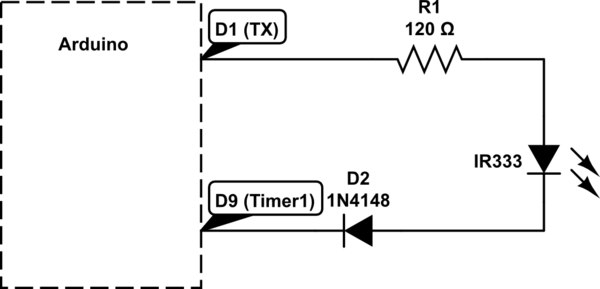
Utilizing a digital infrared (IR) receiver module and a digital IR transmitter module, each connected to separate Arduino Uno boards, the objective is to transmit data, such as "1234", to the receiver and display this data on an LCD....
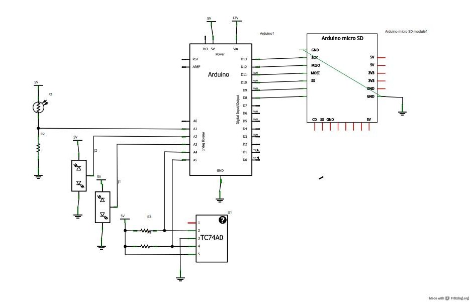
Now that the basics have been covered in tutorials 1-10, it is time to pursue more complex projects. In this episode, an SD card shield from cooking-hacks.com will be utilized to create a data logger. The process of reading...
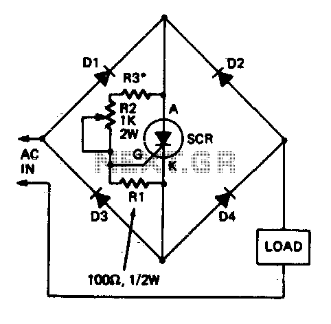
This circuit allows a single Silicon Controlled Rectifier (SCR) to control resistive loads in a full-wave configuration. Resistor R3 must be selected to ensure that when potentiometer R2 is set to its minimum value, the current flowing through the...
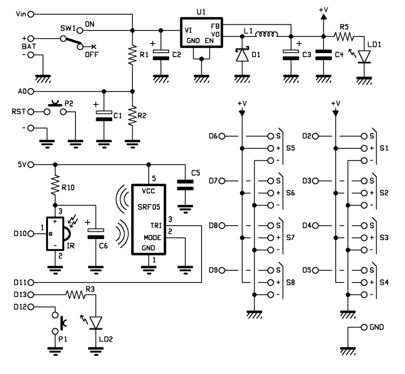
The objective of this project is to consolidate various robot designs and transform them into a new device featuring updated hardware and standardized software, specifically utilizing Arduino for ease of use. These robots share three key components: a mechanical...
Touch screens are increasingly popular, yet many developers have never designed one. This guide provides a step-by-step approach to the necessary hardware and software for successful touch screen implementation. Touch screens are ubiquitous in industrial control systems, consumer electronics,...
Make your own Guitar Effects Pedal with an Arduino board. Bit crushing, rate reducing, weird noises. 10-bit effects/guitar pedal with an Arduino for lo-fi DSP The project involves designing a guitar effects pedal utilizing an Arduino microcontroller to create various...