
FM Radio jammer
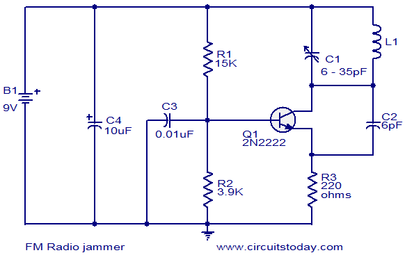
The circuit operates as a simple yet effective VHF oscillator designed to disrupt FM radio signals within its range. The core component, a transistor, is configured in a feedback loop that allows oscillation at VHF frequencies. The selection of components is crucial for achieving the desired frequency range and output power. The use of a 2N2219 transistor instead of the 2N2222 provides an increase in output power, making the circuit more effective.
The oscillation frequency is determined by the values of the inductor (L) and the capacitors (C) in the circuit. The frequency can be tuned precisely using a trimmer capacitor, which adjusts the capacitance in the circuit and hence the oscillation frequency. The formula for calculating the frequency (Fo) generated by the oscillator is essential for ensuring that the circuit operates within the desired frequency band.
Capacitors C2 and C3 can be ceramic, allowing for flexibility in component selection. The use of a 6.8pF capacitor as a substitute for C2 is acceptable, ensuring that the circuit remains functional. The construction of the coil is also critical; while it does not need to be perfectly precise, the number of turns and the diameter will affect the inductance and, consequently, the frequency of oscillation.
To stabilize the frequency further, the circuit can incorporate a crystal oscillator. The crystal's frequency will dictate the jamming frequency, and the circuit can be adjusted to accommodate a crystal with a frequency of 100MHz. Proper connections and component values must be maintained to ensure that the circuit operates as intended.
In summary, this circuit demonstrates the principles of RF oscillation and interference. While it serves as an educational tool for understanding oscillator design, caution must be exercised regarding its legality and ethical use in real-world applications.Circuit shown here can be used to jam FM radios in its vicinity. The circuit is nothing but a classic single transistor oscillator operating in the VHF region. Working principle of the circuit is very simple and straight forward. Powerful VHF oscillations from the circuit will interfere with the FM signals to nullify it. Jammer circuits like this are illegal in many countries and you must assemble this circuit on your own responsibility. This circuit is intended only for fun and i request you not to misuse it. I built it and it works like a charm! To increase power I have to change the 2N2222 with a 2N2219 and replace the power source with a 12V one And regarding the power, in a few words, how can I calculate the emitted power I`d like to ask something about the capacitors. C4 is an electrolytic (polarized) capacitor and it must be installed the proper way, but what about C3 and C2 Can they be ceramic (without any concern for polarization) Also, I couldn`t find a 6pF for C2.
Is 6. 8pF OK ok, I built this on breadboard and it works. I just used a coil a made about a month ago for another schema 16AWG 100 turns on 20 mm diameter plastic tube. How you do the coil doesn`t seem to matter much because you set the frequency from the capacitor. Hi, if I calculate the values for L and C in order for this circuit to jam frequencies in SHF (GHz) will it do it or do I have to change some other component Can the transistor sustain a frequency of say 3GHz Seetharaman, this jammer circuit will work, but will face one problem, the human body capacitance will damped the oscillation in the tank circuit and it can affect the frequency stability.
How do i connect crystal to stabilise the frequency. Please help me if you connect a crystal to the circuit then what ever the crystals frequency is then that is the only frequency that you will be able to jam using this circuit. iF you actually want to still connect a crystal then use a 100MHz on because with the inductor being a coil than the tolerance to the crystal changes to about 97MHz-103MHz (jamming those frequencies only)(tolerance=3%) where to connect (using schematic): joint north of 6 pF cap.
then add 10 ohm (1% or it will screw up the oscillation) resistor on top of it then crystal then connect other end of crystal to coil. the wire joint that comes from south of trimm cap. and goes right connects to the joint between the crystal and the coil in the situation that i have just described If you have the values of capacitor and inductor, you will be able to calculate the frequency generate by the oscillator with this operation: Fo = 1/(2*pi*sqrt(L*C).
Guys I just put this together and IT WORKS ! I used the exact same parts as listed in this schematic minus the transistor. The substitute I used for the 2N2222 transistor was the BC337, you can find that one commonly. Also instead of a 6pF cap I used a 5. 6pF and it still works. You have to pay attention to the trimmer capacitor and turn it using an insulated/non-conductive tool (you can put a plastic bag between the cap and a screwdriver and it ll still work). The inductor doesn t have to be super accurate either. The tuning is super sensitive so you have to get used to that too, it takes some time. The trimmer capacitor doesn t have to be the exact same one, it should just cover its range in terms of capacitance.
Hope I cleared some of your questions out Cheers The legality of the circuit depends on how and where you use it. It is basically a CW generator so a radio will just pick up silence. It differs little from the little transmitters that allow a CD player to be picked up on a nearby radio.
There`s just no input where a mic or CD player could be attached. In most jurisdictions, the limiting factor is SWR. So if it can only be picked up for a few meters, the legality would depend on how you use it. If you`re only interfering with your own radio, it should be alright in most pla 🔗 External reference
Related Circuits
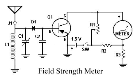
This circuit utilizes a single 1.5V battery. The capacitor C1 must be adjusted for optimal peak reading. To operate the circuit, the transmitter and meter should be turned on. The circuit is designed to operate efficiently with a single 1.5V...
This simple FM radio receiver circuit utilizes the TDA7000 integrated circuit (IC), which incorporates nearly all the necessary functions to construct an FM receiver, requiring only a few external capacitors and a tuning circuit. The design employs a straightforward...
A schematic diagram for a broadband QRP SWR metering circuit intended for use in a QRP antenna tuner. The circuit allows the user to press a momentary DPDT switch to observe an LED indicator while adjusting the capacitors of...
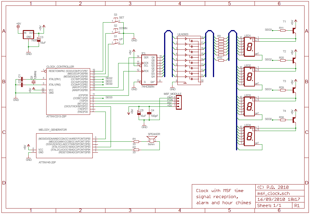
The National Physics Laboratory broadcasts a time signal, previously known as the Rugby clock but now called "Time from NPL." Its most commonly known as the MSF signal due to it originally being identified in Morse code those letters....
In a previous article on constructing a radio, a simple crystal radio receiver circuit was discussed. The schematic presented here is also a straightforward AM radio circuit; however, it does not utilize a crystal but instead employs a high-gain...
The most commonly available headphones have an impedance of 2 × 32 Ω. This relatively low value makes them unsuitable for certain designs. However, with some clever modifications, these headphones can be adapted for such applications. To achieve this,...