
Tube Tune-A-Lite ID37856
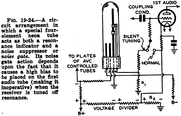
The Tune-a-Lite 4-element neon tube operates under specific electrical characteristics that are crucial for its application as a signal strength indicator. The I/V characteristics observed in the photos highlight the relationship between the cathode current and the voltage across the T terminal. The design of the tube includes a pilot cathode that allows for a gradual increase in brightness, preventing sudden activation, which is a common drawback in simpler tube designs. The operational principle hinges on the cathode's glow reaching a threshold that enables the T terminal to conduct, facilitating the transition from a muted state to an amplified audio output.
In practical applications, the 500kΩ load resistor plays a vital role in stabilizing the operation of the T terminal, ensuring that it remains within the desired operating region. The adjustments made via the potentiometer at the anode are essential for fine-tuning the performance of the tube, allowing for compensation of variations due to factors such as cathode poisoning.
For circuit designers and engineers working with vintage audio equipment, understanding the nuances of this tube's operation is critical for maintaining or enhancing the performance of devices that utilize it. The potential for adapting modern components, such as the IN-13 or IN-9 tubes, offers alternative solutions for users facing challenges in sourcing original parts while preserving the functionality and aesthetic of classic radio designs.The following two photos show the I/V charactereristics of the main Anode/Cathode current for the Tune-a-lite 4 element neon tube used as signal strength meter in some Fada Radios as the Tune-o-graph. The 4 terminal Tuneon tube used in some Cossor radios works similarly to this tube. This first photo shows a low 130V trigger voltage for the main c athode that is approximately the same as the operating the voltage. This low trigger voltage is facilitated by the 100uA current flow through the small pilot cathode. The pilot cathode is seen glowing to the lower right of the main cathode. This tube has some darkening, indicating use. After about one hour of use, the same 5mA maximum current was enough to cover the entire main cathode with glow. The terminal numbering in the photos refers to the convention used with 4 pin tubes, with a clock-wise count starting at the lower left thick pin, when the two thick pins are at the bottom.
The small cathode eliminated the problem that the 2 terminal Tune-a-lite, and similar tubes, have of turning on suddenly, only when voltage is increased greatly after the glow is extinguished. The pilot cathode is present in all 3 terminal and 4 terminal tubes of this type. As the cruve traces below will show, when the cathode glow is below the top of the T, which is to say, with less than 1mA of cathode current, the T terminal behaves as an open circuit.
When the glow reaches the top of the T, the terminal starts conducting suddenly. If the load to the T is just the 500kOhms to ground that is common in the application circuit, the Voltage at the T is about 15V when the glow is even with the top of the T, and increases to 40V at full glow with 5mA of cathode current. Some of the large variation in generated voltage at the T terminal can be due to cathode poisoning that would develop in the cathode after decades of rest.
The cathode poisoning increases plasma potential. I noticed that the glow grew longer after some time, and the postitive bias variation with with glow lenght was less pronounced. When the tube is in use, with the enabling switch under user control, the audio triode stage under control of the Tune-a-Lite is pre-biased below cutoff with a large positive voltage at the cathode, and the triode grid is grounded.
So, between stations, the glow is below the T, and the audio triode remains cut off. When the glow reaches the top of the T, the positive voltage that is developed at the T, provides a bias to the grid of audio stage triode and brings it into conduction and amplification, thus stopping the muting. Astrong station causes the glow to reach the top of the T. With 3-4mA flowing through the cathode, the T terminal starts to fire like a cathode, if drive negative, but in the application, the 500K load resistor to ground keeps it`s conduction on the positive side of the curve, which behave more like a current source.
As compared to similar tubes with only 3 or 2 terminals, this 4 terminal tube requires that the main cathode be grounded for proper operation of the T terminal with respect to the audio triode stage under muting control. The internal glow adjustment in the 4 terminal device is done with a potentiometer at the Anode, while it may be done on either terminal of the 3 and 2 terminal tubes.
Summarizing the operation of the T terminal, it provides a positive high impedance current source into a 500K load when strong stations bring the glow past the top of the T. When the glow is below the T, no bias is developed, and the controlled audio stage remains off to prevent inter-station noise.
If you need a replacement for this very rare tube, you may be able to improvise with a 3 wire IN-13 Russian analog bargraph Tube, or a 2 wire IN-9 version. This article link shows how to add one of these analog bargraph tubes to a common AC/DC 5 tube radio.
🔗 External reference
Related Circuits
The theory of operation has been previously discussed in the Simple Superhet or the All American Five. Constructing this radio is relatively straightforward, especially if the circuits have been followed in the order presented. The variable capacitor used is...
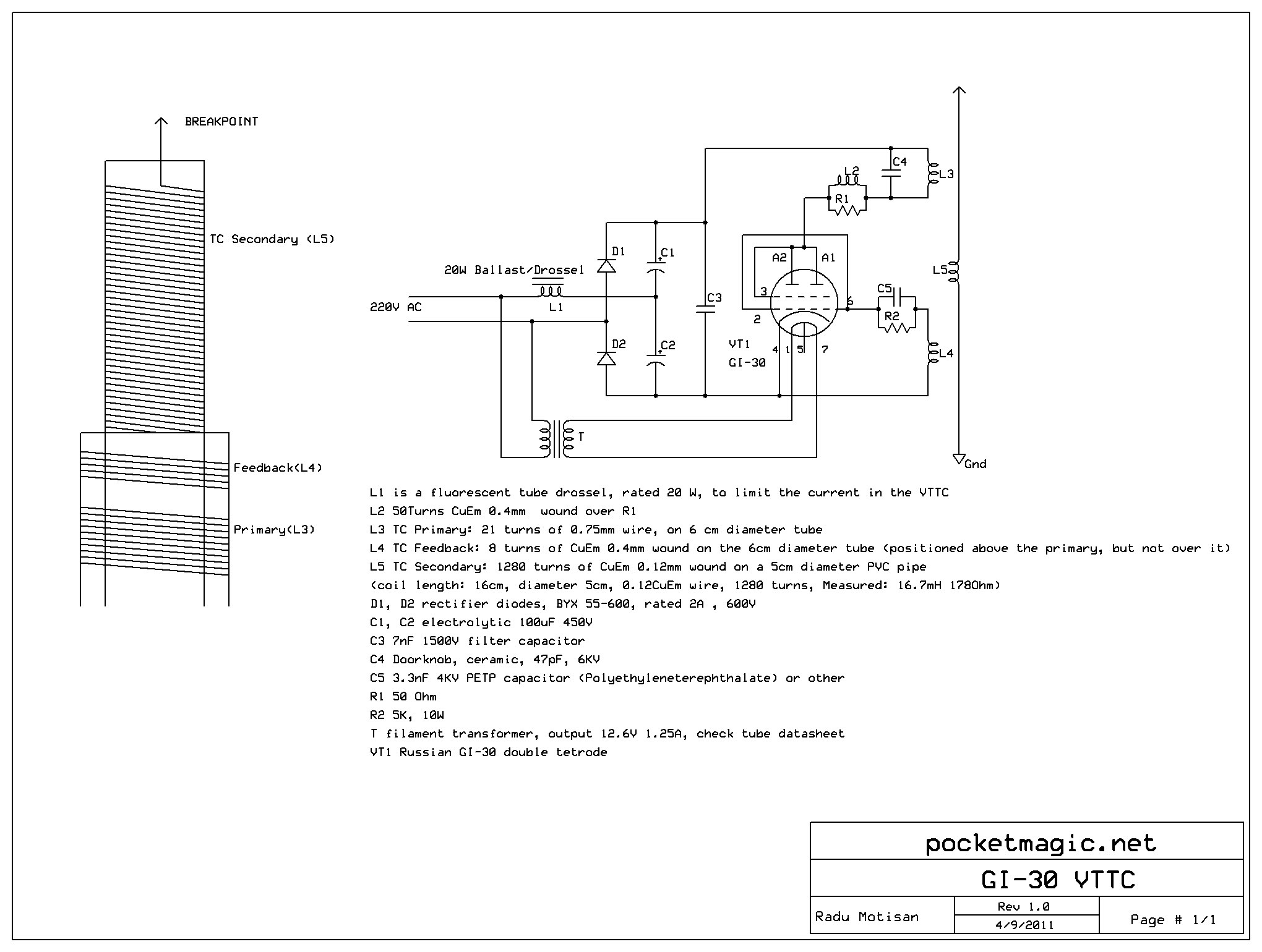
This setup is compact and operates offline directly from a 220V source, utilizing a voltage doubler to elevate the plate voltage to 560V DC. The circuit consists of a simple Armstrong oscillator, employing the feedback coil L4. The design...
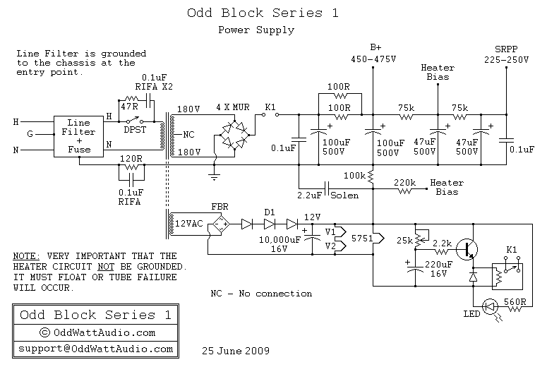
A schematic of the ability accumulation is presented below. Similar to the amplifier schematic, the ability accumulation design is © OddWatt Audio, and permission to host the schematic on this platform has been granted by OddWatt Audio. The schematic...
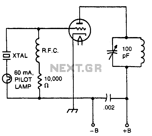
The pilot lamp limits current to prevent damage to the crystal. A very useful circuit. The circuit incorporates a pilot lamp designed to limit the current flowing to a crystal component, thereby safeguarding it from potential damage due to excessive...

One of the advantages of hosting a hobby website is the opportunity to connect with individuals via email who share similar interests. Since posting Bruce's initial OddWatt project on the site, communication has occurred with numerous DIY hobbyists who...
This is a classic design of a 35 W final amplifier utilizing two EL34 tubes in a push-pull configuration, developed by Siemens and Halske. The design dates back to March 24, 1953, and is identified by the code SV410/1....
Warning: include(partials/cookie-banner.php): Failed to open stream: Permission denied in /var/www/html/nextgr/view-circuit.php on line 713
Warning: include(): Failed opening 'partials/cookie-banner.php' for inclusion (include_path='.:/usr/share/php') in /var/www/html/nextgr/view-circuit.php on line 713