
DIY ECG Machine On The Cheap

Measurement: The electrical signals that regulate cardiac muscle activity can be detected on the skin's surface. In theory, one could use a standard voltmeter by holding one lead in each hand to observe voltage changes with each heartbeat. However, these fluctuations are rapid, and by the time they reach the skin, they are extremely weak (on the order of a few millionths of a volt) and challenging to detect with basic devices. Therefore, amplification is necessary.
Amplification: A straightforward method to amplify the electrical difference between two points is to utilize an operational amplifier (op-amp). The gain, or multiplication factor, of an op-amp is adjusted by varying the resistors connected to it. For instance, an op-amp with a gain of 1000 can amplify a 1 millivolt signal to 1 volt. Various types of microchip op-amps are available, often packaged with multiple op-amps in one chip, such as the quad-op-amp LM324 or the dual-op-amp LM358N. Any op-amp designed for low voltage applications is suitable for this project, and only one is required.
Noise: It is essential to consider that the heart's electrical signals can be obscured by noise from other sources. Implementing effective noise reduction techniques is crucial for obtaining clear and accurate ECG readings. This may involve filtering out unwanted frequencies or using differential input configurations to enhance the signal-to-noise ratio.The goal of such a machine (called an electrocardiograph, or ECG ) is to amplify, measure, and record the natural electrical potential created by the heart. Note that cardiac electrical signals are different than heart sounds, which are listened to with a stethoscope.
The intrinsic cardiac pacemaker system is responsible for generating these electrical signals which serve to command and coordinate contraction of the four chambers at the heart at the appropriate intervals [atria (upper chambers) first, then the ventricles (lower chambers) a fraction of a second later], and their analysis reveals a wealth of information about cardiac regulation, as well insights into pathological conditions. Each heartbeat produces a similar pattern in the ECG signal, called a PQRST wave. [ picture ] The smooth curve in the ECG (P) is caused by the stimulation of the atria via the Sinoatrial (SA) node in the right atrium.
There is a brief pause, as the electrical impulse is slowed by the Atrioventricular (AV) node and Purkinje fibers in the bundle of His. The prominent spike in the ECG (the QRS complex) is caused by this step, where the electrical impulse travels through the inter-ventricular septum and up through the outer walls of the ventricles.
The sharp peak is the R component, and exact heart rate can be calculated as the inverse of the R-to-R interval (RRi). Fancy, huh The goal of this project is to generate an extremely cheap, functional ECG machine made from common parts, most of which can be found around your house.
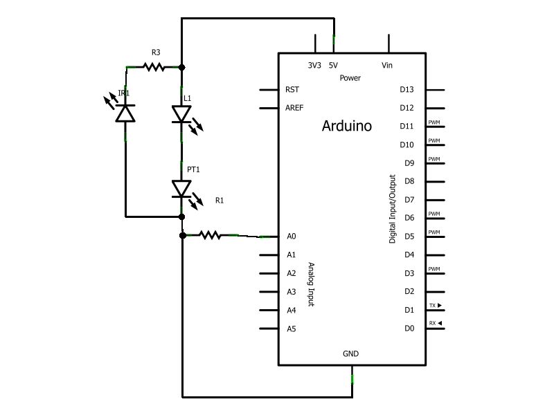
This do-it-yourself (DIY) ECG project is different than many others on the internet in that it greatly simplifies the circuitry by eliminating noise reduction components, accomplishing this via software-based data post-processing. Additionally, this writeup is intended for those without any computer, electrical, or biomedical experience, and should be far less convoluted than the suspiciously-cryptic write-ups currently available online.
In short, I want to give everybody the power to visualize and analyze their own heartbeat! I know a lot of Internet readers aren`t big fans of reading. Therefore, I provided an outline of the process in video form. Check out the videos, and if you like what you see read more! Measurement: The electrical signals which command cardiac musculature can be detected on the surface of the skin. In theory one could grab the two leads of a standard volt meter, one with each hand, and see the voltage change as their heart beats, but the fluctuations are rapid and by the time these signals reach the skin they are extremely weak (a few millionths of a volt) and difficult to detect with simple devices.
Therefore, amplification is needed. Amplification: A simple way to amplify the electrical difference between two points is to use a operational amplifier, otherwise known as an op-amp. The gain (multiplication factor) of an op-amp is controlled by varying the resistors attached to it, and an op-amp with a gain of 1000 will take a 1 millivolt signal and amplify it to 1 volt.
There are many different types of microchip op-amps, and they`re often packaged with multiple op-amps in one chip (such as the quad-op-amp lm324, or the dual-op-amp lm358n ). Any op-amp designed for low voltage will do for our purposes, and we only need one. Noise: Unfortunately, the heart is not the o 🔗 External reference
Related Circuits
Have you ever wanted to create a line-following robot but found infrared sensors too expensive? If you are located in the UK and have access to a Maplin store nearby, you can purchase infrared transmitters and receivers for just...
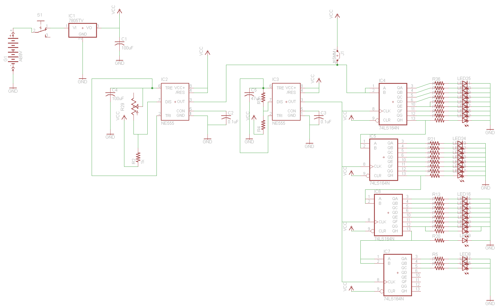
For the two-layer board schematic, six core integrated circuits (ICs) will be utilized: four 74LS164 shift registers and two 555 timers. The schematic will be constructed using the Eagle Layout Editor, as all required components are available in its...
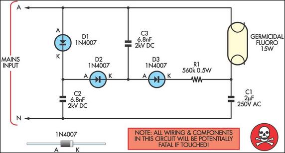
This simple circuit can start small (15W or less) fluorescent tubes, such as those used in PC board exposure and EPROM ultraviolet erasure boxes. The tube's filament heaters are not utilized. Instead, ignition is provided by a voltage tripler...
LED 1 will light and the buzzer turns on when the coil is changing inductance. The setup is easy, VR1 is adjusted (away from any metal objects) so that LED 1 will light and the buzzer sounds on, and...
This article outlines the construction of an opto-isolated power switch designed for controlling heavy loads using logic-level signals. An opto-isolated power switch is an essential component in many electronic systems, particularly when interfacing low-voltage control circuits with high-voltage or high-current...
The circuit is straightforward, utilizing a single IC chip, the ICL8038 function generator chip, which produces simultaneous sine, square, and sawtooth waveforms. The circuit consists of a minimal number of components, including two resistors, one transistor, five trimpots, and...