
DIY Homemade Ignition Coil Driver

The ignition coil serves as a crucial component in creating high-voltage power supplies, leveraging the principles of electromagnetic induction. The operation of the ignition coil is based on the rapid change of current in the primary winding, which induces a high voltage in the secondary winding due to the coil's design. The square wave generator circuit is essential for driving the ignition coil, as it provides the necessary rapid on-off switching required to generate high voltage.
For optimal performance, the circuit should be designed to minimize losses and ensure that the transistor or switching device can handle the high-frequency operation without overheating. Heat sinks may be required to dissipate excess heat generated during operation. Additionally, the layout of the circuit should consider minimizing inductive loops and using short, direct connections to reduce parasitic inductance and capacitance, which can lead to inefficiencies and unwanted oscillations.
The use of snubbers, such as RC networks or MOVs, is critical in protecting the circuit from voltage spikes caused by the inductive nature of the ignition coil. Proper selection of snubber components based on the operating frequency and load characteristics can enhance the reliability of the circuit. It is also advisable to implement a robust grounding scheme to prevent ground loops and ensure stable operation.
In summary, the design of a high-voltage ignition coil driver requires careful consideration of component selection, circuit layout, and protective measures to ensure reliable and efficient operation.One of the simplest ways to make a battery powered High Voltage power supply is to use a common car ignition coil. Ignition coils are a type of induction transformer based on the Tesla Coil invented by Nikola Tesla in 1891.
The voltage rise is not given by the turns ratio like in a standard transformer, but is proportional to therate of change ofcurrentin the primary circuit. This means to get a high output voltage you must be able to stop the power flowing into the coil as quickly as possible. In old cars this was simply done mechanically. For use as a HV power supply this needs to happen rapidly over and over. To do this a spacial square wave power supply is uses which switches power on and off to the coil hundreds or thousands of times per second. Standard ignition coils can be obtained from most car parts stores for around £25. It is not essential to use two 12V batteries like shown in the circuits shown below, but it will allow you to obtain bigger sparks.
We have some compact induction coils available for sale for under £20. Click the link to check stock. This driver circuit is based on the commonly used 2n3055 transistor due to it high power switching capability. While these are cheap and high temperature tolerant, they are susceptible to voltage spikes caused by the inductive nature of the load (ignition coil).
Pretty much any power transistor, IGBT or MOSFET can be used in this circuit as long as it is rated for at last 5A and 100V. Ones with higher voltage ratings will be less likely to be damaged by spikes. Further protection methods are outlined lower down this page and in the comments. If you use a MOSFET or IGBT instead of a bipolar transistor like the 2n3055, you should also add a pulldown resistor of about 10k between the base/gate pin and GND.
This next circuit is designed for a higher powered output. Two ignition Coils are connected in parallel but with opposite polarity. This means that the output voltages of each coil are out of phase or opposite to each other (when one is positive, the other is negative). Using this configuration the output is taken from the two coils output terminals, whereas the circuit above uses the output terminal and ground.
These circuits will work great for driving ignition coils for high voltage but they can be susceptible to damage from inductive spikes. When an ignition coil is being driven unloaded (open circuit on the output) there will be significantly increased back emf and risk of damaging the driver circuit.
We sell an ignition coil driver module which has built in protection against most spikes that would damage a driver. It also includes an early warning indicator which will show you how severe the back emf is from your load.
If you build an ignition coil driver to make high voltage sparks and arcs, you will need some sort of EMI protection for your circuit. Without it, it is very likely you will destroy the transistors or driver ICs. Snubbers are a tricky subject, but in general they are used to reduce electromagnetic interference (EMI) or voltage spikes.
There are many ways to reduce EMI and it can often be useful to use various snubbers in different parts of the circuit. These diagrams represent a few possible ways you can snub EMI in an ignition coil driver. These are known as dissipative snubbers because the excess energy is disspated as heat or light. The top digram uses a series connected capacitor and resistor. The values used will depend on your drive frequency. (See RC1 at top of this page). Generally speaking, a bigger capacitance and smaller resistance will snub more, but also absorb more drive power thefore reducing efficiency.
A compromise must be found that best suits your setup. The next diagram uses a device known as a MOV ( Metal Oxide Varistor ). These are semiconductor devices which will only begin conducting when the voltage between its terminals exceeds its rated value. It will stop co 🔗 External reference
Related Circuits
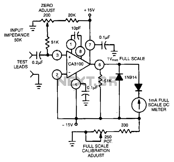
This circuit utilizes the CA3100 BiMOS operational amplifier to drive a 1-mA meter movement to its full scale with a 1-V RMS input. The circuit configuration incorporates the CA3100 BiMOS operational amplifier, which is known for its high input impedance...
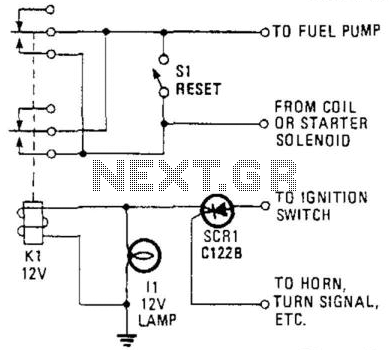
This circuit utilizes a combination of a silicon-controlled rectifier (SCR) and a relay to interrupt the ignition system unless a positive voltage is applied to the gate of the SCR. This configuration serves as an anti-theft device, as the...
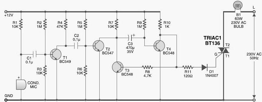
This DIY sound-activated lights circuit turns a lamp on for a brief duration when a dog barks or when a relatively loud sound is detected, creating the impression that the occupants are alerted. The condenser microphone is positioned to...
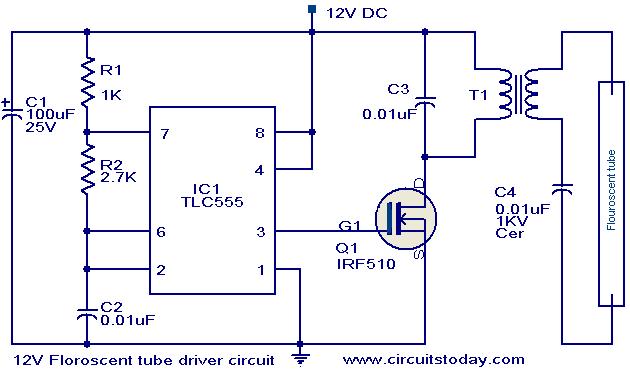
This circuit provides a simple and effective method for driving fluorescent lamps using a 12 V power supply. The circuit consists of an oscillator, a MOSFET switch, and a step-up transformer to power the fluorescent lamp. The TLC 555...
The NP-100v12 is a straightforward headphone amplifier designed for entry-level builders to assemble and listen to their own creation. The term "builder" refers to individuals with electronic experience and innovation, allowing them to create a device rather than merely...
The preamplifier described is engineered with a low output impedance, specifically designed to handle long cable runs. This feature allows for listening to a remote music source without the need for expensive screened cables. The preamplifier boasts a very low...