
DIY Sound Activated LightsCircuit

This sound-activated lights circuit is designed to provide an automated lighting solution based on auditory stimuli, particularly useful in scenarios involving pets or security. The circuit's core components consist of a condenser microphone, transistors for amplification, and a triac for controlling the light output.
The condenser microphone serves as the primary sensor, converting sound waves into electrical signals. These signals are AC in nature and are first processed by the DC blocking capacitor (C1), which prevents any DC component from affecting the subsequent transistor stages. The BC549 transistor (T1) acts as an initial amplifier, increasing the strength of the audio signals. The second transistor (T2) further amplifies these signals, ensuring that sufficient current is available to trigger the triac.
The triac (BT136) is a semiconductor device that allows current to flow through the load (bulb B1) when it is triggered by a gate signal, in this case, from the collector of T2. The design allows the bulb to remain lit for a predetermined duration (approximately two minutes) after the initial sound is detected, providing a visual alert.
For assembly, it is recommended to use a general-purpose PCB to accommodate the components neatly and securely. A 12V power supply is suitable for this circuit, and the step-down transformer should be chosen to provide adequate current (500mA) to ensure reliable operation. Proper soldering techniques should be employed, especially for the triac, to prevent any potential short circuits due to close pin spacing.
Placement of the entire unit is crucial for optimal performance. The microphone should be positioned to effectively capture sounds from the desired monitoring area, and enclosing it in a tube can significantly enhance its sensitivity to sounds, ensuring reliable activation of the lighting circuit. The overall design is compact and can be easily integrated into various environments, providing a practical solution for sound-activated lighting.This diy sound activated lights circuit turns a lamp ON for a brief length when the canine barks (or a somewhat strong sound) providing an impression that the occupants happen to be alerted. The condenser microphone fitted in a place to watch sound and generates AC signals, which pass by means of DC blocking capacitor C1 for the base of transistor
BC549 (T1). Transistor T1 along with transistor T2 amplifies the sound signals and offers existing pulses in the collector of T2. When audio is produced in front from the condenser mic, triac1 (BT136) fires, activates lights plus the bulb (B1) glows for about two minutes.
Assemble the sound activated lights circuit on a general objective PCB (circuit board) and enclose inside a plastic cabinet. Energy for the sound activated change circuit is often derived from a 12V, 500mA step-down transformer with rectifier and smoothing capacitor.
Solder the triac making sure adequate spacing among the pins to avoid short circuit. Resolve the unit within the dog`s cage or shut to the audio monitoring spot, using the lamp within or outdoors as sought after. Connect the microphone for the sount activated lights circuit employing a brief size of shielded wire.
Enclose the microphone inside a tube to increase its sensitivity. 🔗 External reference
Related Circuits
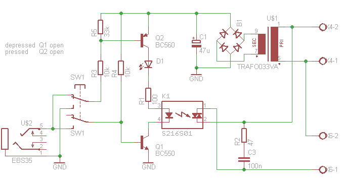
This article outlines the construction of an opto-isolated power switch designed for controlling heavy loads using logic-level signals. An opto-isolated power switch is an essential component in many electronic systems, particularly when interfacing low-voltage control circuits with high-voltage or high-current...
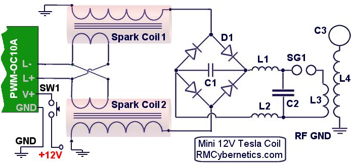
The DIY Plasma Gun is a compact, homemade Tesla Coil gun powered by an 18V battery. It features a specialized plasma discharge terminal capable of emitting ionized gas and flames. The entire system is housed within the casing of...
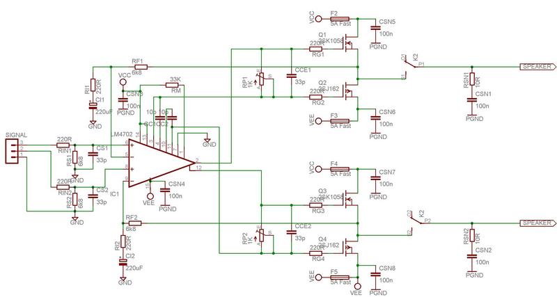
The LM4702 has been integrated into a Crown DC150 amplifier. The driver board in the Crown was damaged, but the power supply remains functional. The LM4702 is a high-performance audio amplifier IC designed for use in various audio applications, including...
A simple and interesting project schematic for a cell phone signal-activated LED circuit. The circuit will illuminate an LED when a call is made from a cell phone. This cell phone signal-activated LED circuit utilizes a basic principle of detecting...
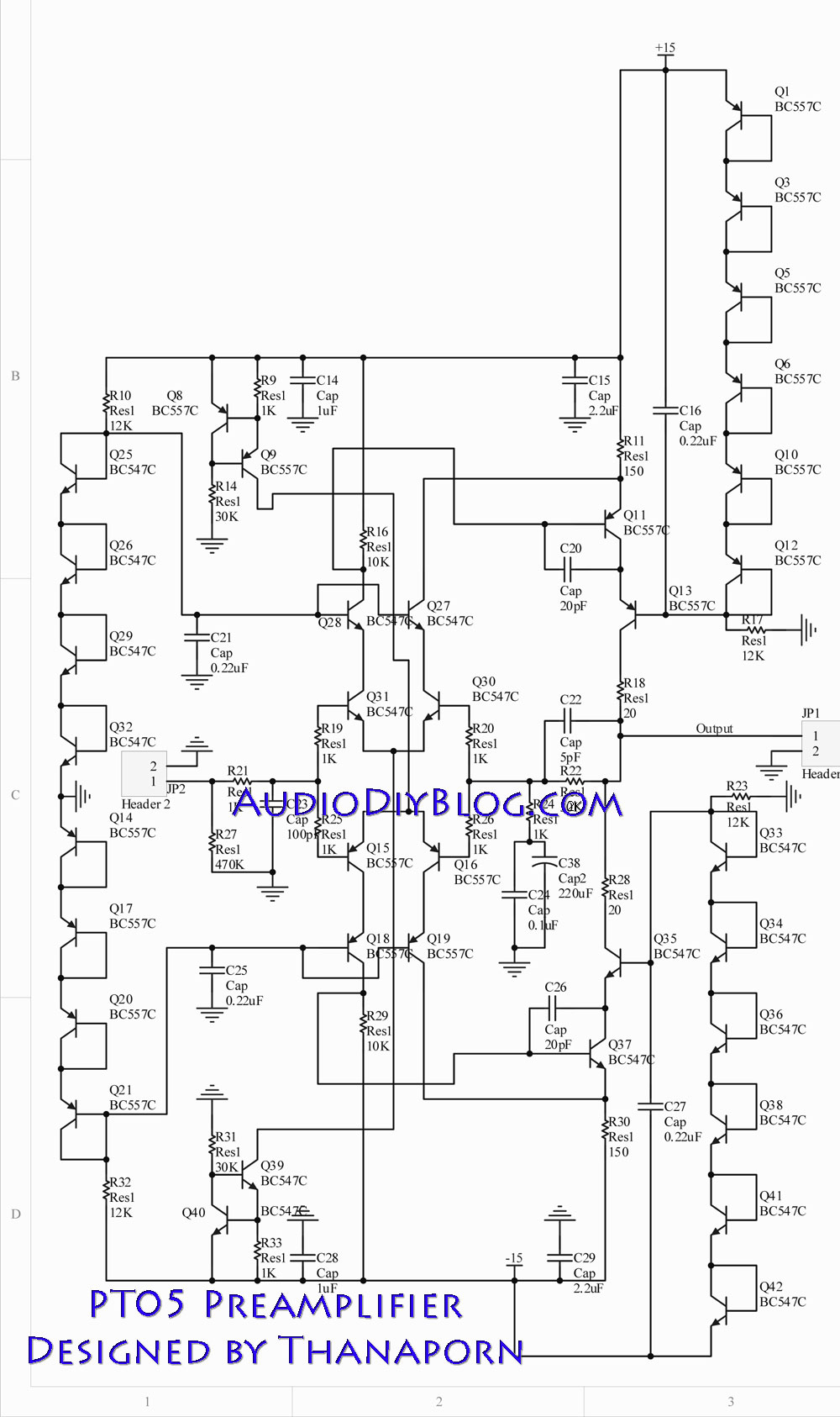
The next stage operates in conjunction with the first stage and is fully complementary. A cascode circuit is included to enhance the linearity of the amplifiers. This cascode circuit requires a constant reference voltage for biasing to activate the...
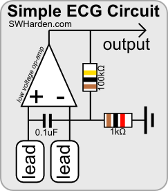
The purpose of an electrocardiograph (ECG) is to amplify, measure, and record the natural electrical potential generated by the heart. It is important to note that cardiac electrical signals are distinct from heart sounds, which are detected using a...