
DIY Solar Tracker System Circuit
The described solar tracker circuit employs a simple yet effective design to maximize solar energy capture. The use of four LDRs arranged in a specific configuration allows for precise detection of light intensity from different angles. The window comparator circuit is crucial for determining the relative brightness on each LDR, effectively comparing their outputs to ascertain which side is receiving more sunlight. The transistors serve as switches that control the motor's direction based on the comparator's output. This mechanism allows the panels to continuously adjust throughout the day, following the sun’s trajectory across the sky.
For implementation, the circuit requires a power supply compatible with the motor specifications, ensuring that the maximum current does not exceed 300 mA to prevent damage to the components. The LDRs should be selected for their sensitivity to the wavelengths of sunlight, and their placement must be optimized to avoid shadows from the panels themselves. The potentiometers P1 and P2 are integral for fine-tuning the sensitivity of the circuit, allowing for adjustments based on environmental conditions or specific tracking requirements.
In summary, this analog solar tracker circuit facilitates efficient solar energy harvesting by dynamically adjusting the orientation of solar panels in response to sunlight variations, thereby enhancing the overall energy capture efficiency. For applications requiring vertical tracking, additional circuitry would need to be designed to complement the current system, ensuring comprehensive solar tracking capabilities.When the sun position is changing so does the illumination level on the LDRs and the input voltage for the window comparator is no longer half of the supply voltage thereby the output of the comparator generates informations for the motor that rotates the panels for tracking the sun. P1 and P2 are adjusted in such way that the motor stands still w hen the LDRs get the same amount of solar light. If less light reaches LDR2 than LDR1, the voltage in point A increases to more than half of the power supply voltage. As a result the output of A1 is HIGH and T1 and T4 transistors conduct. In this situation the motor is starting. If the angle of the solar light is changing again and the voltage in point A decreases at less than power supply voltage, the output of A2 goes HIGH and T3 and T2 transistors conduct.
As a result the motor is rotating in opposite direction. For solar panels control is best to use small motors with a suitable voltage and a maximum working current of 300 mA. This solar tracker system is used for tracking the sun only in one plane, the horizontal one. If you want to track the solar light in the vertical plane you need to build a separate sun tracker circuit.
This is a simple and practical analog solar panel tracker circuit. Using four LDR (light dependent resistor) as a sensor in detecting the light source arranged as illustrated. When the light hit the LDR in a certain position, it will activate the circuit and trigger the relay to turn the slewing motor in the right direction until the sensor is fully shaded under its cover stopping the motor to its rest condition.
🔗 External reference
Related Circuits
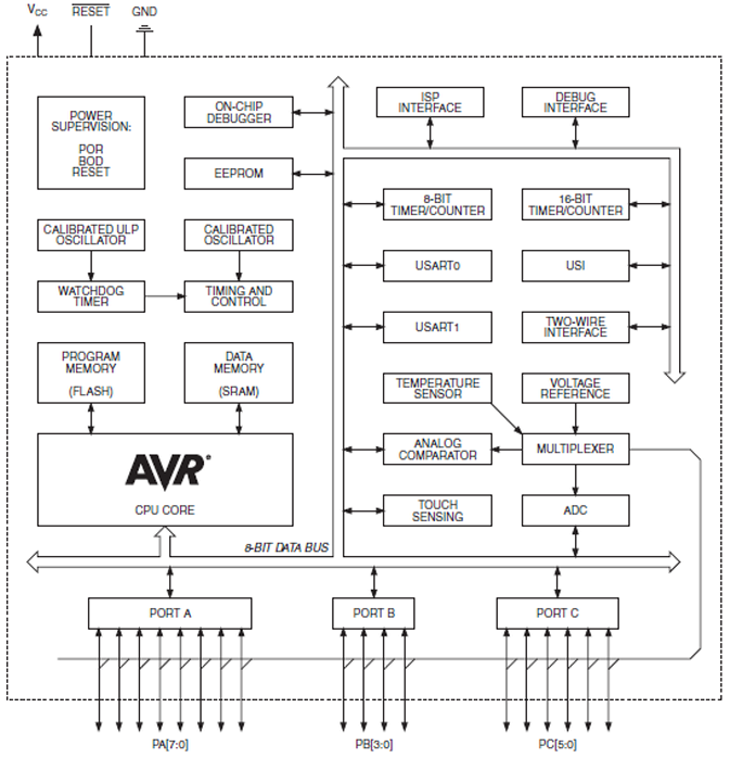
The ATtiny1634 8-Bit AVR Microcontroller from Atmel is based on the enhanced RISC architecture of AVR. It can execute powerful instructions in a single clock cycle, achieving throughputs close to 1 MIPS per MHz. This allows system designers to...

If circuits experience frequency overvoltage conditions, continually replacing blown fuses can become quite costly. This shutdown circuit addresses that issue by substituting the fuse with a relay and a low-current SCR. When the input voltage exceeds the threshold established...
You may be familiar with this effect. You switch audio equipment such as an amplifier to a different input and there is a loud click or "thump" in the speaker system. Not all equipment is affected. Some high-end audio...

The program utilizes the internal 4 MHz oscillator of the PIC16F628 microcontroller in a two-input alarm circuit. The two-input alarm circuit designed with the PIC16F628 microcontroller leverages the internal 4 MHz oscillator to provide a stable clock signal for operation....
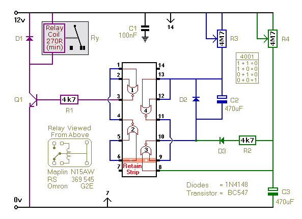
This timer utilizes a basic monostable circuit. The duration for which the relay remains energized, referred to as the ON period, is regulated by the resistor R3 and capacitor C2. Conversely, the duration for which the relay remains de-energized,...

This is a design circuit diagram of a moderate power FM transmitter circuit. The circuit operates using two transistors. It consists of a complete circuit diagram. The operation of this circuit is explained as follows: the voice signals picked...
Warning: include(partials/cookie-banner.php): Failed to open stream: Permission denied in /var/www/html/nextgr/view-circuit.php on line 713
Warning: include(): Failed opening 'partials/cookie-banner.php' for inclusion (include_path='.:/usr/share/php') in /var/www/html/nextgr/view-circuit.php on line 713