
DIY Arduino Nebulophone Synth

The circuit design involves an AtMega 328 microcontroller programmed via ArduinoISP, which serves as the core component for the Nebulophone functionality. This microcontroller offers flexibility and programmability, enabling the creation of sound output similar to that of a Nebulophone. The DoAnything Shield expands the capabilities of the Arduino by providing multiple GPIO (General Purpose Input/Output) pins, allowing for versatile connections of various components.
The circuit integrates a SPST or SPDT slide switch, which serves as a user interface element, enabling the user to toggle the device on and off. The choice between SPST and SPDT does not impact functionality, as the second terminal of the SPDT switch remains unused. This switch can be implemented in various forms, such as toggle or rocker switches, providing options for user preference.
The LED and photocell assembly is critical for the light-sensing functionality of the circuit. The LED emits light, which is detected by the photocell, allowing for interaction based on light levels. The suggested construction of this assembly involves a simple bending of the LED towards the photocell, encapsulated in black tubing to prevent interference from ambient light. The resistance of the photocell plays a significant role in determining the sensitivity of the light detection, and a range of 10k to 200k is typically effective for this application.
Overall, this circuit provides a cost-effective and customizable solution for creating a Nebulophone-like device, leveraging existing Arduino technology and enabling further exploration into sound synthesis and user interaction through light sensing.I originally wanted to purchase a Nebulophone but, my El-Cheapo price range didn`t like the tag. I realized that I could program my own AtMega 328 by using ArduinoISP Then I found out that if the code was Arduino compatible, why not just use the Arduino as a Nebulophone Well it was kind of a waste of Arduino but at least I could simplify circuitr y. I recently built my DoAnything Shield and could now have access to any pin I wanted. I looked at the schematic and realized that Dr. Bleep had left plenty of things missing such as where did the stylus go and, where were the keypads and so I emailed him and after a long string of emails everything was cleared up. 1 SPST/SPDT slide switch (Any type of switch that can move from one position to another until pused again work (Toggle, Rocker, etc.
) It doesn`t matter whether it is SPST or SPDT the second connection is nothing. ) 1 LED and Photocell assembly (I got mine from here but I didn`t realize that the same website had this which is much cheaper although untested. You could also make your own by bending an LED over to a photocell that can range from 10k to 200k. and then covering it with some black tubing. I`m not sure the one I had is exactly 10k to 200k but it worked. ) 🔗 External reference
Related Circuits
A very simple DIY crystal oscillator circuit that uses a quartz crystal for frequency stability and a suitable RF transistor. It employs a second or third harmonic crystal for operation. This DIY crystal oscillator circuit is designed to generate stable...

The provided connections will enable configuration-free usage for most Arduino boards. Some Arduino boards, such as the Mega2560, may require custom configuration due to how the ports on the Atmel AVR microcontroller are mapped to the digital pins on...
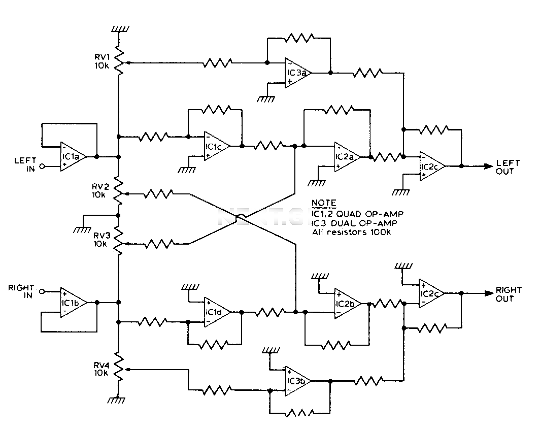
This circuit synthesizes two rear channels for quadraphonic sound when provided with a stereo signal. The rear output for the left channel is created by combining the left channel input, which is 180 degrees out of phase, with a...
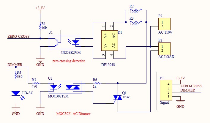
Have you verified whether you can see the zero crossings on your input pin? It may be beneficial to write a sketch that toggles the LED on pin 13 every 50 or 60 zero crossings. This should result in...
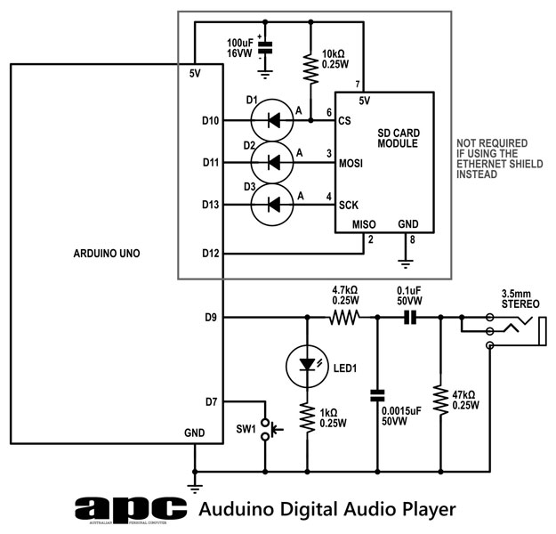
In this series, a diverse exploration of how Arduino interacts with various real-world devices has been presented, from servo motors to ultrasonic range finders, TVs to humidity sensors. The focus now shifts to generating sound using Arduino. The project...
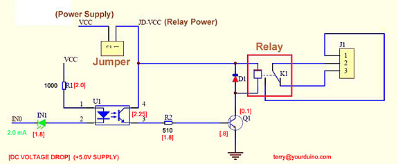
Control a relay from an Arduino-compatible board. When attempting to activate the relay from the Arduino, it takes at least a second to close, and sometimes it does not close at all. Digital pin 2 of the Arduino is...