
DIY intervalometer for Sony NEX

The intervalometer setup involves an Arduino microcontroller interfacing with a Serial LCD and an infrared LED to control the camera shutter. The LCD is initialized with an I2C address of 0x27, supporting a 16x2 character display. The joystick module is utilized to adjust the interval between shots and to navigate the menu. The joystick's X-axis is connected to Analog 0, the Y-axis to Analog 1, and the Z-axis button to Digital 2 of the Arduino.
In the setup function, the pin modes are configured, and the LCD is initialized. The loop function continuously reads the joystick's position to determine user input. Depending on the joystick's position, the interval for capturing images can be adjusted. When the joystick button is pressed, the intervalometer enters a working mode where it captures images at the specified interval. The onboard LED provides visual feedback during operation.
The software includes functions to display the menu and the current working status on the LCD. The intervalometer can automatically turn off the LCD backlight after a specified duration of inactivity to conserve power. The code structure includes error handling for joystick inputs and ensures the interval remains within a valid range. The integration of the infrared LED allows for triggering the camera shutter remotely, making it suitable for time-lapse photography projects.A DIY intervalometer for my Sony NEX 5N camera so that I could do time-lapse photography. This intervalometer should work with most Sony cameras: NEX, Alpha and other. To work intervalometer used infrared LED Serial LCD has 4 output: GND, VCC, SDA, SCL. SDA (data) connect to Arduino Analog In 4, SCL (clock) connect to Analog In 5. Vcc connect to 5V Arduino, and GND connect to GND Arduino. Circuit is powered by 9V battery. Battery positive output connected to the input Vin Arduino. Arduino has a built-5V voltage converter that we need to power the Serial LCD. The anode of the IR LED is connected through current limiting resistor and connected to 10-pin Arduino. Cathode of the IR LED connected to GND. // Article // Version 1. 0 #include "Wire. h" #include "LiquidCrystal_I2C. h" #define axis_X 0 // axis X of Joystic connected to Analog 0 #define axis_Y 1 // axis Y of Joystic connected to Analog 1 #define axis_Z 2 // axis-button Z of Joystic connected to Digital 2 #define pinIRLED 10 // IR LED #define LEDgreen 13 // onboard LED #define autoOFF 10 // autoOFF backlight LCD LiquidCrystal_I2C lcd(0x27, 16, 2); // set the LCD address to 0x27 for a 16 chars and 2 line display int value_X, value_Y, value_Z = 0; // axis values int pos = 0; // current position (0 - delay, 1 - work) int interval = 1; // pause between shots (sec) int cntPict = 0; // shots count boolean working = false; unsigned long currentTime; unsigned long TimeShot, TimeLCDOff; void setup() { pinMode(axis_Z, INPUT); // Joystic button pinMode(pinIRLED, OUTPUT); // IR LED lcd.
init(); // init LCD lcd. backlight(); // turn LCD backlight ON lcd. clear(); // clear LCD show_menu(); // function show menu currentTime = millis(); TimeShot = currentTime; // shots timer TimeLCDOff = currentTime; // backlight timer //Serial. begin(115200); } void loop() { value_X = analogRead(axis_X); // read the analog value of the X axis value_Y = analogRead(axis_Y); // read the analog value of the Y axis value_Z = digitalRead(axis_Z); // read the digital value of the Z axis (button) value_Z = value_Z1; // invert the value if(working = false){ if(value_Y > 540){ // joystick up pos = 0; lcd.
backlight(); // LCD backlight ON TimeLCDOff = currentTime; // new value of TimeLCDOff show_menu(); } else if(value_Y < 500){ // joystick down pos = 1; lcd. backlight(); // LCD backlight ON TimeLCDOff = currentTime; // new value of TimeLCDOff show_menu(); } if(value_X > 530){ // joystick left lcd.
backlight(); // LCD backlight ON TimeLCDOff = currentTime; // new value of TimeLCDOff if(pos = 0){ -interval; if(value_X > 900) interval = interval-10; // joystick full left if(interval < 1) interval = 1; } show_menu(); } else if(value_X < 490){ // joystick right lcd. backlight(); // LCD backlight ON TimeLCDOff = currentTime; // new value of TimeLCDOff if(pos = 0) { +interval; if(value_X < 100) interval = interval+10; // joystick full right } show_menu(); } } if(value_Z = 1){ // joystick button press lcd.
backlight(); // LCD backlight ON TimeLCDOff = currentTime; if(working = true){ working = false; pos = 0; show_menu(); } if(pos = 1) show_working(); // turn on work mode } delay(200); currentTime = millis(); if(working = true){ if(currentTime >= (TimeShot + (interval*1000){ digitalWrite(LEDgreen, HIGH); // blink onboard LED delay(100); digitalWrite(LEDgreen, LOW); takePicture(); // send IR TimeShot = currentTime; +cntPict; // increase the counter shots show_working(); // refresh LCD } } if(currentTime >= (TimeLCDOff + (autoOFF*1000){ lcd. noBacklight(); // LCD backlight OFF } } void show_menu() { cntPict = 0; // zero out counter shots lcd.
clear(); lcd. setCursor(0, pos); lcd. print("*"); // current position lcd. setCursor(1, 0); lcd. print("delay:"); lcd. setCursor(8, 0); lcd. print(interval); lcd. setCursor(1, 1); lcd. print("go work"); } void show_working() { lcd. clear(); lcd. setCursor(3, 0); 🔗 External reference
Related Circuits

Amblone stands for AmbiLight Clone, and it is a Do It Yourself solution for imitating the Philips AmbiLight system. Amblone is designed to replicate the AmbiLight technology developed by Philips, which enhances the viewing experience by projecting ambient light that...
The system includes a CD player, amplifier, speakers, power supply, and headphones. The Mitsumi CD player, designed for the United States, features a 4-speed CD-ROM launched in mainland China in 1997, equipped with an out-of-box key panel for speed...
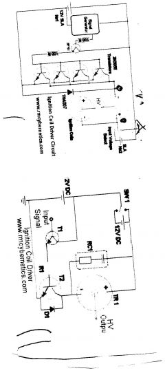
One of the simplest methods to create a battery-powered high-voltage power supply is by utilizing a common car ignition coil. Ignition coils function as a type of induction transformer, inspired by the Tesla Coil invented by Nikola Tesla in...
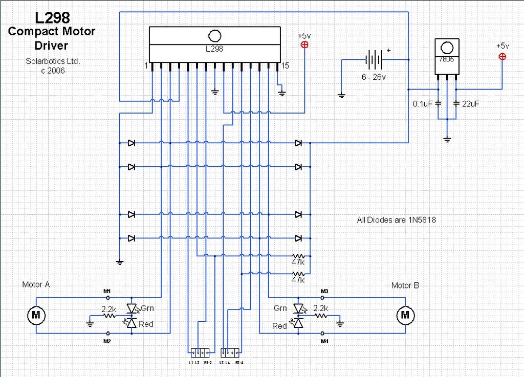
The ArduinoISP Bootloader/Programmer Combination Shield (not displayed) works with an Arduino equipped with a USB to serial chip (e.g., Arduino Uno) to upload the bootloader and sketches to a DIYduino. A USB to Serial programmer can also be utilized...
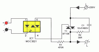
The primary advantage of a solid-state relay (SSR) over a traditional electromagnetic relay (EMR) is its reduced wear and tear, which enhances its longevity. The S201S01 model from Clear-Cut serves as an exemplary representation of this technology. The following...
The 15 kHz frequency is used to drive the flyback transformer; however, the high voltage at the output is DC. The flyback transformer operates by converting low-voltage DC into high-voltage DC, utilizing a specific driving frequency, in this case, 15...