
DIY Micromitter Stereo FM Transmitter
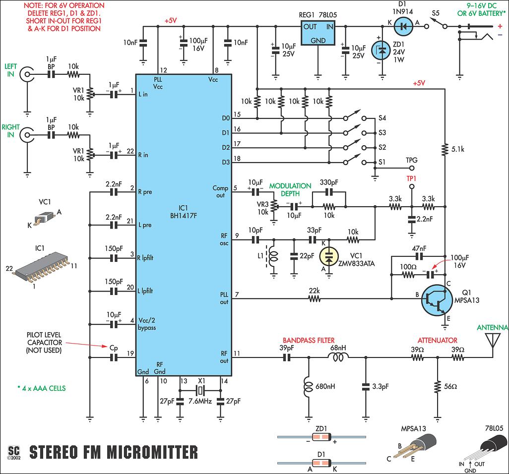
The FM Micromitter circuit operates by utilizing the BH1417F IC, which integrates key components necessary for FM transmission, including audio processing, modulation, and frequency stability features. The DIP switch configuration allows the user to select from a range of preset frequencies, which simplifies setup and eliminates the need for complex tuning procedures. The crystal locking feature enhances frequency stability, making it suitable for various applications, including home audio systems and portable devices. The pre-emphasis circuit is crucial for maintaining audio quality, ensuring that higher frequencies are transmitted effectively and received with minimal noise interference. The overall design is compact and user-friendly, making it accessible for hobbyists and professionals alike who require a reliable FM transmission solution. The schematic would typically include connections for the power supply, audio input, output to the antenna, and the DIP switch configuration, ensuring that all components are correctly integrated for optimal performance.This new stereo FM Micromitter is capable of broadcasting good quality signals over a range of about 20 metres. It`s ideal for broadcasting music from a CD player or from any other source so that it can be picked up in another location.
For example, if you don`t have a CD player in you car, you can use the Micromitter to broadcast signals from a p ortable CD player to your car`s radio. Alternatively, you might want to use the Micromitter to broadcast signals from your lounge-room CD player to an FM receiver located in another part of the house or by the pool. Because it`s based on a single IC, this unit is a snack to build and fits easily into a small plastic utility box.
It broadcasts on the FM band (ie, 88-108MHz) so that its signal can be received on any standard FM tuner or portable radio. However, unlike previous FM transmitters published in SILICON CHIP, this new design is not continuously variable over the FM broadcast band.
Instead, a 4-way DIP switch is used to select one of 14 preset frequencies. These are available in two ranges covering from 87. 7-88. 9MHz and 106. 7-107. 9MHz in 0. 2MHz steps. We first published an FM stereo transmitter in SILICON CHIP in October 1988 and followed this up with a new version in April 2001. Dubbed the Minimitter, these earlier versions were based on the popular Rohm BA1404 IC which is not being produced any more.
On both these earlier units, the alignment procedure requires careful adjustment of the ferrite tuning slugs within two coils (an oscillator coil and a filter coil), so that the RF output matched the frequency selected on the FM receiver. However, some constructors had difficulty with this because the adjustment was quite sensitive. In particular, if you had a digital (ie, synthesised) FM receiver, you had to set the receiver to a particular frequency and then carefully tune the transmitter frequency "through" it.
In addition, there was some interaction between the oscillator and filter coil adjustments and this confused some people. That problem doesn`t exist on this new design, since there is no frequency alignment procedure. Instead, all you have to do is set the transmitter frequency using the 4-way DIP switch and then dial-up the programmed frequency on your FM tuner.
The new FM Stereo Micromitter is now crystal-locked which means that the unit does not drift off frequency over time. In addition, the distortion, stereo separation, signal-to-noise ratio and stereo locking are much improved on this new unit compared to the earlier designs.
The specifications panel has further details. Fig. 2: this frequency versus output level plot shows the composite level (pin 5). The 50ms pre-emphasis at around 3kHz causes the rise in response, while the 15kHz low pass roll off produces the fall in response above 10kHz. At the heart of the new design is the BH1417F FM stereo transmitter IC made by the Rhom Corporation. As already mentioned, it replaces the now hard to find BA1404 that has been used in the previous designs.
Fig. 1 shows the internal features of the BH1417F. It includes all the processing circuitry required for stereo FM transmission and also the crystal control section which provides precise frequency locking. As shown, the BH1417F includes two separate audio processing sections, for the left and right channels.
The left-channel audio signal is applied to pin 22 of the chip, while the right channel signal is applied to pin 1. These audio signals are then applied to a pre-emphasis circuit which boosts those frequencies above a 50ms time constant (ie, those frequencies above 3.
183kHz) prior to transmission. Basically, pre-emphasis is used to improve the signal-to-noise ratio of the received FM signal. It works by using a complementary de-emphasis circuit in the receiver to attenuate the boosted treble frequencies after demodulation, so that the frequency response is restored to normal. At the same time, this 🔗 External reference
Related Circuits
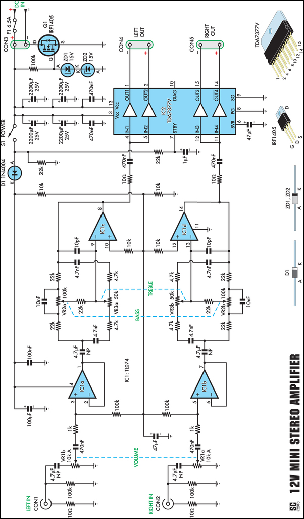
Amplifiers that operate on 12V DC typically do not produce significant power and are often not high fidelity. However, this compact stereo amplifier meets the requirements for power and low distortion. With a supply voltage of 14.4V, it can...
This circuit is a simple two transistor (2N2222) FM transmitter. No license is required for this transmitter according to FCC regulations regarding wireless microphones. If powered by a 9 volt battery and used with an antenna no longer than...
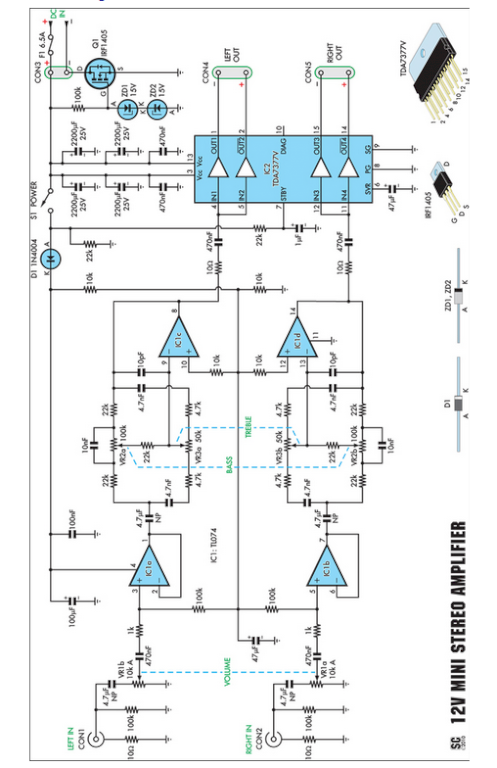
Amplifiers that operate on 12V DC typically do not deliver significant power and are often not classified as high-fidelity (hifi) devices. However, this compact stereo amplifier meets the power requirements effectively. This compact stereo amplifier is designed to operate efficiently...
There are many ways to create a stereo effect. If you were miking a piano, a string section, or some other large sound source, you would probably stick up a pair of directional mikes and assign them left and...
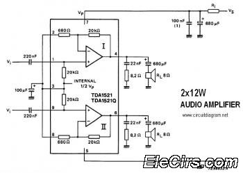
This is a stereo audio amplifier circuit that delivers 12W output power for each audio channel. The circuit is constructed using a single integrated circuit, the TDA1521 or TDA1521Q, and is supported by a minimal number of external components. The...
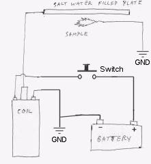
Instructions for constructing a simple Kirlian effect camera to capture high voltage corona discharges around objects, also referred to as aura photography. The Kirlian effect is a phenomenon where high voltage electrical discharges create a visual representation of the energy...