
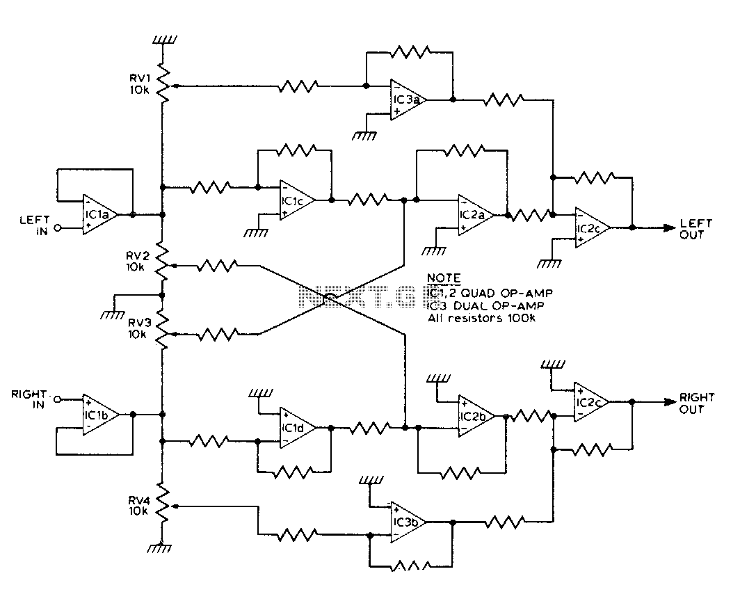
Stereo Synthesizer
The creation of a stereo effect in audio engineering can be achieved through various methods, especially when dealing with mono sources such as lead vocals, electric guitars, or synthesizers. The use of two directional microphones positioned strategically can capture spatial information effectively when recording larger sound sources like pianos or string sections. For enhancing the stereo image of mono instruments, techniques such as delaying one channel or utilizing pitch-shifting devices like Harmonizers can be employed.
However, it is crucial to consider the implications of these methods on mono compatibility. When an audio signal is processed to create a stereo effect, the phase relationship between the left and right channels can be altered. This can lead to issues when the audio is played back on mono systems, where elements of the mix may cancel each other out, resulting in a loss of clarity or presence.
In terms of frequency management, the design of the stereo processing system can be optimized by employing crossover filters. These filters can separate the audio signal into different frequency bands, allowing for targeted processing of each band. For instance, frequencies below 200 Hz can be assigned to one channel, while higher frequencies can be directed to the other. This technique not only enhances the stereo effect but also maintains the integrity of the audio signal across various playback systems.
The implementation of such a system requires careful consideration of the crossover points and the corresponding adjustments of the controls to achieve the desired stereo image without compromising the overall mix. Visual aids, such as graphs depicting the frequency response, can assist in understanding how different settings affect the stereo output, ensuring that the audio engineer can make informed decisions during the mixing process.There are many ways to create a stereo effect. If you were miking a piano, a string section, or some other large sound source, you`d probably stick up a pair of directional mikes and assign them left and right. But what if you want to "enlarge" a lead vocalist? Or, how about other inherently mono instruments like an electric guitar or a synthesizer? Well, you could delay one side or use a Harmonizer or some other related gadgetry, but generally with this method the stronger the effect you create, the more you`ll jeopardize mono compatibility.
As mentioned earlier, different frequency ranges appear at the two outputs, depending on the setting of the controls. To be a little more specific, the actual crossover points are as follows (it helps to look at the graph): Frequencies below 200 Hz.
are a 🔗 External reference
Related Circuits
An FM modulator that modulates a carrier frequency with the composite signal, and an RF amplifier that provides enough power to be transmitted through an antenna. Here is the schematic diagram of the FM transmitter circuit: The core of...
This circuit synthesizes two rear channels for quadraphonic sound when provided with a stereo signal. The rear output for the left channel is created by combining the left channel input, which is 180 degrees out of phase, with a...

This stereo amplifier utilizes the NE5517/A and features an excellent tracking accuracy of 0.3 dB, which is typical. The offset can be adjusted using the potentiometer, Rp. For AC-coupled amplifiers, the potentiometer can be substituted with two 5.1 k...
This application note describes the evaluation board for the AD7892-2, a 12-bit analog-to-digital (A/D) converter. The AD7892-2 is a high-speed, low-power device capable of 500 ksps sampling rate, operating from a single +5V supply. It features an on-chip track/hold...
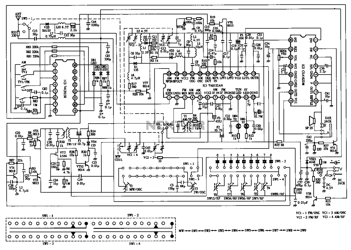
The circuit diagram for the Desheng 119 700 type FM, TV sound, medium wave, and short wave high sensitivity L2-band stereo radio is presented below. The Desheng 119 700 type radio circuit is designed to receive various frequency bands including...
The following circuit illustrates the IC BA1404 used in a stereo FM transmitter circuit diagram. Features include ease of construction, making it accessible for anyone to build. The BA1404 is a versatile integrated circuit designed specifically for FM transmission applications....
Warning: include(partials/cookie-banner.php): Failed to open stream: Permission denied in /var/www/html/nextgr/view-circuit.php on line 713
Warning: include(): Failed opening 'partials/cookie-banner.php' for inclusion (include_path='.:/usr/share/php') in /var/www/html/nextgr/view-circuit.php on line 713