
FM transmitter 2N2222
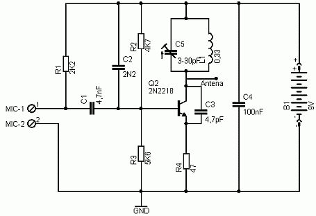
The described FM transmitter circuit employs two 2N2222 transistors, where Q1 serves as the microphone amplifier. The audio signal from the microphone is fed to the base of Q1, which increases the signal strength before it is sent to the second transistor, Q2. The amplified audio signal modulates the oscillator circuit formed by Q2, C5, and L1, allowing the transmitter to operate within the FM frequency range of 80 to 130 MHz.
The oscillator's frequency can be fine-tuned by adjusting the components in the tank circuit, specifically L1 and C6. The inductor L1 is constructed from two parallel strands of 24 gauge insulated wire, coiled around a pencil to create a compact and effective inductor. This method of construction ensures that the inductor is both functional and easily reproducible.
C6 is a makeshift capacitor formed by twisting a piece of wire, which provides the necessary capacitance for the oscillator circuit. The twisted wire acts as a variable capacitor, allowing for minor adjustments in the oscillator frequency.
R6 functions as a current-limiting resistor, protecting the RF section from excessive input levels. Its value can be modified to adjust the input signal level to the desired volume, ensuring optimal performance of the transmitter without distortion.
The antenna is a simple length of 24 gauge wire, cut to a length of 8 to 12 inches, which is soldered to the inductor. This antenna length is compliant with FCC regulations, ensuring that the transmitter operates legally and effectively within the designated frequency range.
Overall, this circuit represents a straightforward and practical approach to building a small FM transmitter suitable for personal use, adhering to legal requirements and providing a functional understanding of basic RF principles.This circuit is a simple two transistor (2N2222) FM transmitter. No license is required for this transmitter according to FCC regulations regarding wireless microphones. If powered by a 9 volt battery and used with an antenna no longer than 12 inches, the transmitter will be within the FCC limits.
The microphone is amplified by Q1. Q2, C5, and L1 form an oscillator that operates in the 80 to 130 MHz range. The oscillator is voltage controlled, so it is modulated by the audio signal that is applied to the base of Q2. R6 limits the input to the RF section, and it's value can be adjusted as necessary to limit the volume of the input.
L1 and C6 can be made with wire and a pencil. The inductor (L1) is made by winding two pieces of 24 gauge insulated wire, laid side by side, around a pencil six times. Remove the coil you have formed and unscrew the two coils apart from each other. One of these coils (the better looking of the two) will be used in the tank circuit, and the other can be used in the next one you build.
The antenna (24 gauge wire) should be soldered to the coil you made, about 2 turns up from the bottom, on the transistor side, and should be 8-12 inches long. To make C6, take a 4 inch piece of 24 gauge insulated wire, bend it over double and, beginning 1/2" from the open end, twist the wire as if you were forming a rope.
When you have about 1" of twisted wire, stop and cut the looped end off, leaving about 1/2" of twisted wire (this forms the capacitor) and 1/2" of untwisted wire for leads. 🔗 External reference
Related Circuits
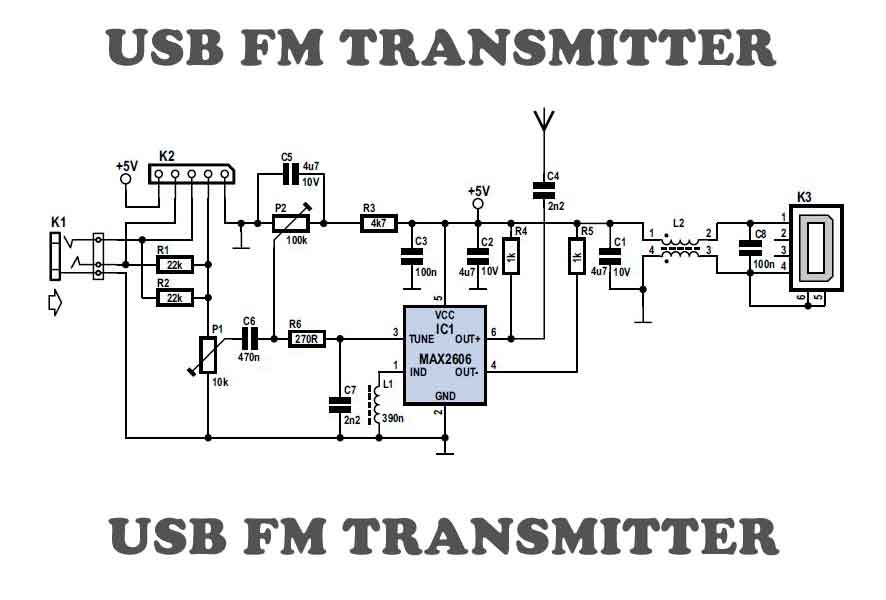
To test VHF receivers independently from local radio stations, a frequency-modulated oscillator is required, covering the range of 89.5 to 108 MHz. Building such an oscillator with discrete components is challenging. The MAX260x series from Maxim offers five integrated...
A simple whole house FM transmitter circuit diagram and description. Operating power is a 1.5V battery of any type. This circuit is able to transmit at a distance of 30 meters. The whole house FM transmitter circuit operates on a...
This circuit allows for the construction of a compact tracking transmitter that can be detected using an FM broadcast band radio receiver. The transmitter operates on a power source of any 1.5V battery or power supply. It has a...
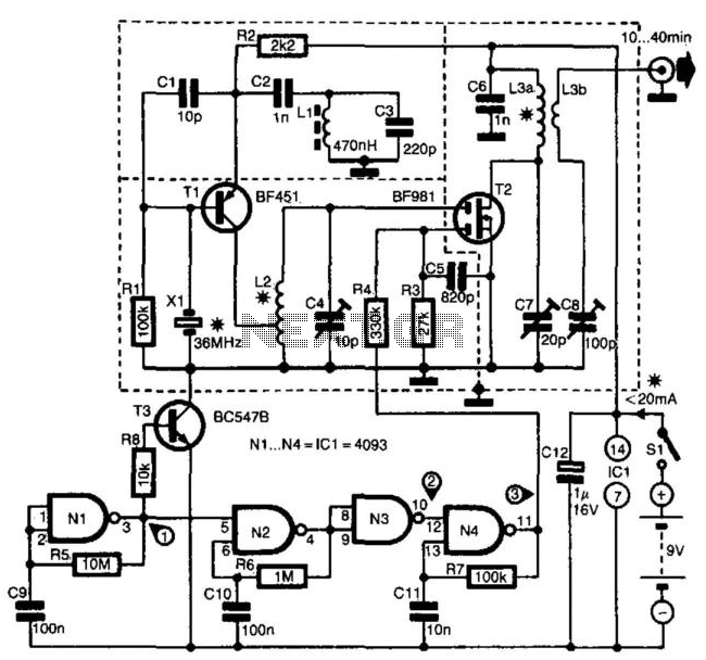
The transmitter is specifically designed for radio amateurs to function as a radio beacon, delivering a high-quality signal devoid of unwanted harmonics. Transistor T1, in conjunction with crystal X1, serves as a 36-MHz oscillator. Filter L1/C3 prevents the circuit...
This is a simple FM transmitter circuit utilizing a medium power 2N2218 transistor. An electret type microphone is connected to two input terminals, and the antenna should be a copper wire measuring between 15 to 40 cm. Below is...
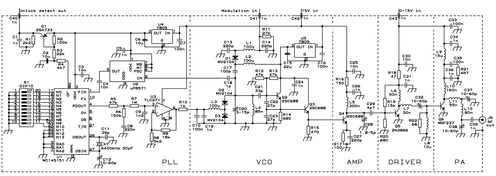
The PLL transmitter exciter is designed to provide a stable, low noise, frequency-selectable RF signal, which is amplified to a controllable output power sufficient to drive a power amplifier. It utilizes a PLL frequency synthesizer based on the MC145151,...
Warning: include(partials/cookie-banner.php): Failed to open stream: Permission denied in /var/www/html/nextgr/view-circuit.php on line 713
Warning: include(): Failed opening 'partials/cookie-banner.php' for inclusion (include_path='.:/usr/share/php') in /var/www/html/nextgr/view-circuit.php on line 713