
diy project actual good canon 5d audio

To commence, a stepped audio file was created in Adobe Audition, covering the frequency range of 20-200 Hz in 20 Hz increments, 200 Hz to 1 kHz in 100 Hz increments, and 1 kHz to 20 kHz in 1 kHz increments. This audio file was uploaded to the SD card of the Marantz field recorder. Playback of this audio into the camera was facilitated through a simple resistor divider circuit, which adjusted for the level difference between the line output and microphone input. The resulting audio waveform extracted from the 5D video file was analyzed, revealing that the left channel waveform, representing the default frequency response of the 5D audio mic input, was influenced by the resistor divider. The right channel waveform demonstrated the effects of the resistor divider along with a custom-designed pre-emphasis circuit. Normalized results were plotted in Excel for better visualization.
The findings indicated that the 5D incorporates a high-pass filter at approximately 120 Hz, while the compensation circuit has a high-pass filter around 60 Hz. The default Canon filter tends to produce a nasal sound. Several trade-offs were made during the design process. The components used were those available on hand, which may not have been optimal but were sufficient for achieving acceptable engineering performance. Additionally, some input loss was accepted in the pre-emphasis circuit to prevent audio clipping when boosting lower frequencies. A reduction of 5-6 dB in signal was chosen to position the high-pass filter point (60 Hz) below the frequency response of human speech, maintaining a favorable signal-to-noise ratio. To adjust for this, the manual audio level on the 5D should be set to 7, ensuring a proper match between the Marantz field recorder and the 5D within design tolerances.
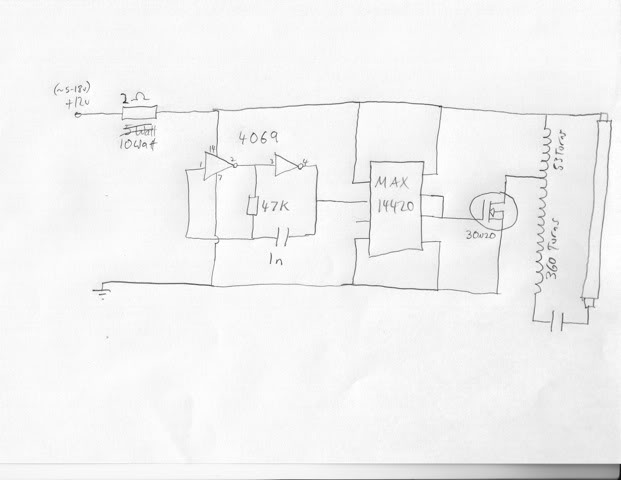
The resulting pre-emphasis filter circuit is straightforward to construct, and due to cost considerations, a printed circuit board (PCB) was not created. Point-to-point soldering was deemed sufficiently robust for practical use. The circuit has demonstrated durability through extensive handling and has been effectively utilized in a 48-hour filmmaking competition. Testing with both shotgun and lavalier microphones yielded satisfactory results for various small production requirements.
The schematic for the pre-emphasis filter circuit includes a series of resistors and capacitors arranged to form the desired frequency response characteristics. A resistor divider is implemented to lower the signal level appropriately for the microphone input. Capacitors are strategically placed to create the high-pass filter effect, allowing lower frequencies to be amplified while preventing clipping. The design ensures that the audio captured by the Canon 5D Mark II is of sufficient quality for production use, making it a viable solution for filmmakers seeking improved audio performance from this camera model.Improving the Canon 5D Mark II audio so that it can produce usable production audio. The first part of any engineering effort is data gathering, so I set about to measure the input frequency response of the 5D. My end goal was to use the Marantz PMD661 field recorderas a mic pre-amp and primary production audiorecorder, however I also wanted to take the audio line output from the field recorder and feed it into the 5D to
capture "good enough" production audio. To start off I created a stepped audiofile in Adobe Audition (20-200Hz: 20Hz steps, 200-1KHz: 100Hz steps, 1kHz-20kHz: 1kHz steps) andupload it to the Marantz field recorder SD card. Then it was simply a matter of playing back the audio into the camera with a simple resistor dividercircuit to compensate for the level difference between a line out and a mic input.
The stepped audio waveform you see below is the audio extracted from the 5D video file. The top (left channel) waveform is simple resistor divider that also represents the defaultfrequency response of the 5D audio mic input. The bottom(right channel) waveform is the effect of the resistor divider, pluscustom designedpre-emphasis circuit.
I also plotted thenormalizedresults in Excel to make the data a little easier to see. The bottom line:The 5D has a highpass filter at about 120Hz. Thecompensation circuit has a high pass around60Hz. The default Canon filter makes people sound like Gilbert Gottfried with a cold. Like any design there were some trade-offs. The first, and foremost, is that I had to use whatever components I had sitting around the test bench, sort of like the cook in the kitchen with a bunch of semi-random ingredients. No, my filter components aren`t necessarily optimal but they`re good enough to get the job done with respectable engineering designmargin.
Second, I had to accept some input loss for the pre-emphasis circuit because the purpose of the circuit is to boost the lower frequencies. If you boost the lower (60-200Hz) frequencies without lowering the input signal you`ll get audio clipping, which is even worse than a nasty/nasal-y high pass filter.
Here I chose to trade off 5-6dB in signal because it put my high pass filter point (60Hz) well below the frequency response of human speech. I could have traded off more signal for more lower frequencies, but it seemed counter-productive to the signal-to-noise ratio.
. just my engineering judgement. To compensate, just set the 5D manual audio level to 7 (starting from 0). This sets the audio level between the Marantz field recorder and 5D to exactly match (within design margin). A different5D manual audio level settingmay allow you to use the circuit with the Zoom H4N, but I don`t have one to test nor know much about it.
The resulting pre-emphasis filter circuit is shown below. It`s pretty simply to build really. It wasn`t worth it, monetary-wise, to build a PCB, so I didn`t. Point to point soldering, as in the first photo of this blog entry, was sufficiently robust. Believe me, the circuit has already been tossed around, beaten down, and generally production abused like a car in a Micheal Bay film. I recently used it during a 48 hour film making competition. What was the result Well, I can say that I`ve tried it with both a shotgun mic and a lav and found the results were good enough for most small production needs.
I doubt Rodney Charters, Gale 🔗 External reference
Related Circuits
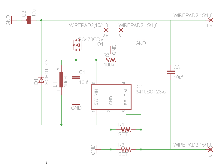
How would you like free boost driver designs? Although it is not possible to control anyone's actions, any individual interested in selling this circuit would be appreciated. The boost driver circuit is a type of DC-DC converter designed to step...
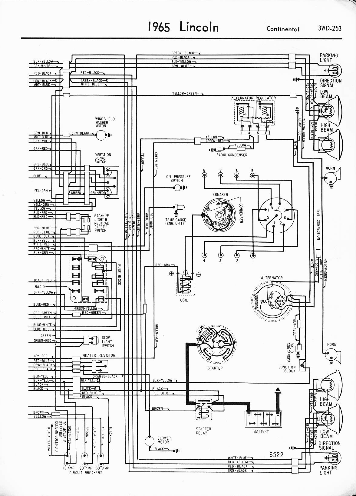
A 1971 Lincoln Continental 4-door is experiencing a complete power failure inside the vehicle, particularly affecting the ignition switch. The battery cables, post connectors, and fusible link have been checked and are functioning correctly. All fuses in the fuse...
This compact device serves as a replacement for the input transistors and related circuitry on a single TO-220 style package. A decision was made to substitute the original driver board with a newly fabricated printed circuit board (PCB) designed...
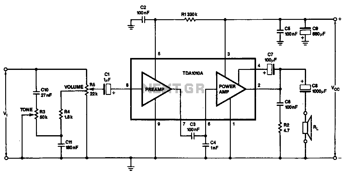
This monolithic IC, class-B audio amplifier circuit is a 6-W car radio amplifier for use with 4-ohm and 2-ohm load impedances. The monolithic integrated circuit (IC) described is designed to function as a Class-B audio amplifier, specifically tailored for...
The lighting hood of the AquaOne AR-320 tank typically comes with low-quality tubes that have inadequate power output and a color spectrum conducive to algae growth. Various improvement methods exist, such as replacing the hood with a metal halide...
This LED (Light Emitting Diode) display consists of 10 LEDs to indicate the level of an input signal. If the signal is low, only LED #1 will light up. As the signal level increases, the illuminated dot will progress...