
Triangular Wave Generator Circuit
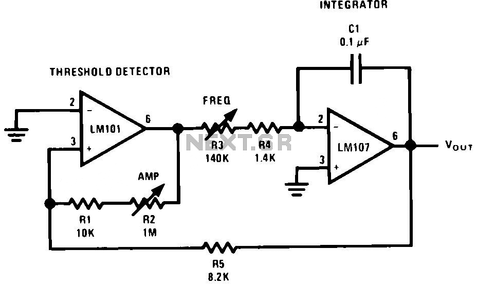
The described circuit operates as a continuous oscillatory system, producing a triangular waveform through the interaction of the integrator and the threshold detector. The integrator serves to convert the current input from the threshold detector into a voltage ramp, while the threshold detector's hysteresis ensures stable transitions between states, preventing noise from causing false triggering. The design employs an operational amplifier configured with feedback resistors that set the gain and define the thresholds for switching.
The resistors R3 and R4 create a voltage divider that influences the input to the integrator, while capacitor C1 determines the rate of ramp generation by controlling the time constant of the integrator circuit. The relationship between the currents I+ and I- and their respective rates of change is crucial for maintaining the symmetry of the triangular waveform. This symmetry is essential in applications where precise timing or frequency is required, such as in signal generation or modulation systems.
In practical implementations, careful selection of the operational amplifier is necessary to ensure it can handle the expected voltage levels and bandwidth. Additionally, the resistors and capacitor must be chosen to achieve the desired frequency and amplitude characteristics, taking into account tolerances that may affect the performance of the circuit. The output can be further processed or utilized in various applications, including waveform generation for testing or as a control signal in automated systems.The generator embodies an integrator as a ramp generator and a threshold detector with hysterisis as a reset circuit. The integrator has been described in a previous section and requires no further explanation. The threshold detector is similar to a Schmitt Trigger in that it is a latch circuit with a large dead zone.
This function is implemented by using positive feedback around an operational amplifier. When the amplifier output is in either the positive or negative saturated state, the positive feedback network provides a voltage at the non-inverting input which is determined by the attenuation of the feedback loop and the saturation voltage of the amplifier. To cause the amplifier to change states, the voltage at the input of the amplifier must be caused to change polarity by an amount in excess of the amplifier input offset voltage.
When this is done the amplifier saturates in the opposite direction and remains in that state until the voltage at its input again reverses. Here is a schematic drawing : The complete circuit operation may be understood by examining the operation with the output of the threshold detector in the positive state.
The detector positive saturation voltage is applied to the integrator summing junction through the combination R3 and R4 causing a current I+ to flow. The integrator then generates a negative-going ramp with a rate of I+/C1 volts per second until its output equals the negative trip point of the threshold detector.
The threshold detector then changes to the negative output state and supplies a negative current, I-, at the integrator summing point. The integrator now generates a positive-going ramp with a rate of I -/C1 volts per second until its output equals the positive trip point of the threshold detector where the detector again changes output state and the cycle repeats.
Triangular-wave frequency is determined by R3, R4 and C1 and the positive and negative saturation voltages of the amplifier A1. Amplitude is determined by the ratio of R5 to the combination of R1 and R2 and the threshold detector saturation voltages.
Positive and negative ramp rates are equal and positive and negative peaks are equal if the detector has equal positive and negative saturation voltages. The output waveform may be offset with respect to ground if the inverting input of the threshold detector, A1, is offset with respect to ground.
🔗 External reference
Related Circuits
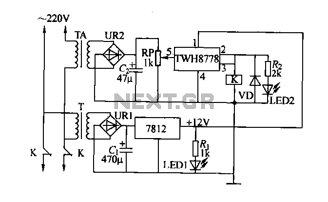
An electric power limiter circuit restricts the user load, ensuring that household appliances operate within a specified normal current range. When the load exceeds a predetermined threshold, the power supply is disconnected. This circuit utilizes the high-power integrated TWH8778...
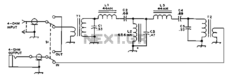
The circuit provides an 8-ohm output for connecting communication receivers and low-impedance speakers or headphones, featuring harmful interference suppression for continuous random voice transmission. The passband ranges from 55 to 2530 Hz with a 3 dB bandwidth. Inductors L1...
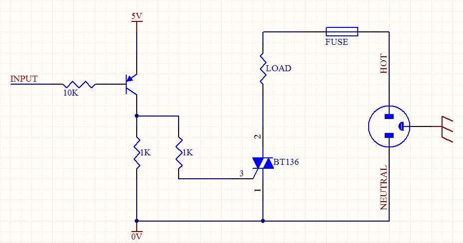
A circuit was designed to function as a light dimmer, utilizing a BT136 SCR and an MOC3022 optocoupler. However, the circuit did not operate as intended. The circuit aims to control the brightness of a light source through phase control...
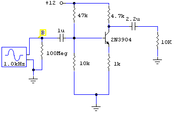
To measure the input impedance of an unknown circuit, first set the signal generator to a current source with a magnitude of 1 amp. A shunt resistor of 100 megohms is also required. This setup is beneficial for measuring...
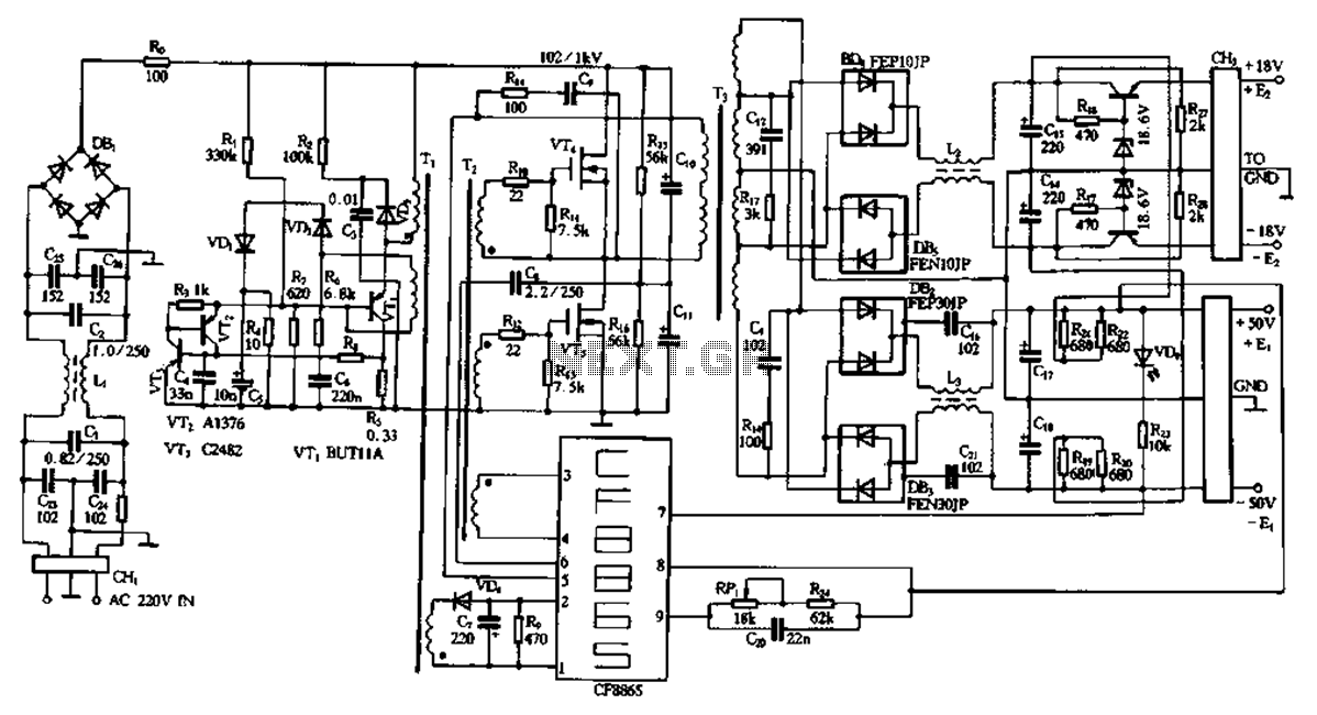
This document describes a specific module utilizing the CF8865 switching power supply circuit, which employs the integrated control module CF8865. In the figure, transistors VT4 and VTs are controlled by the excitation transformer Tz. The output is processed through...
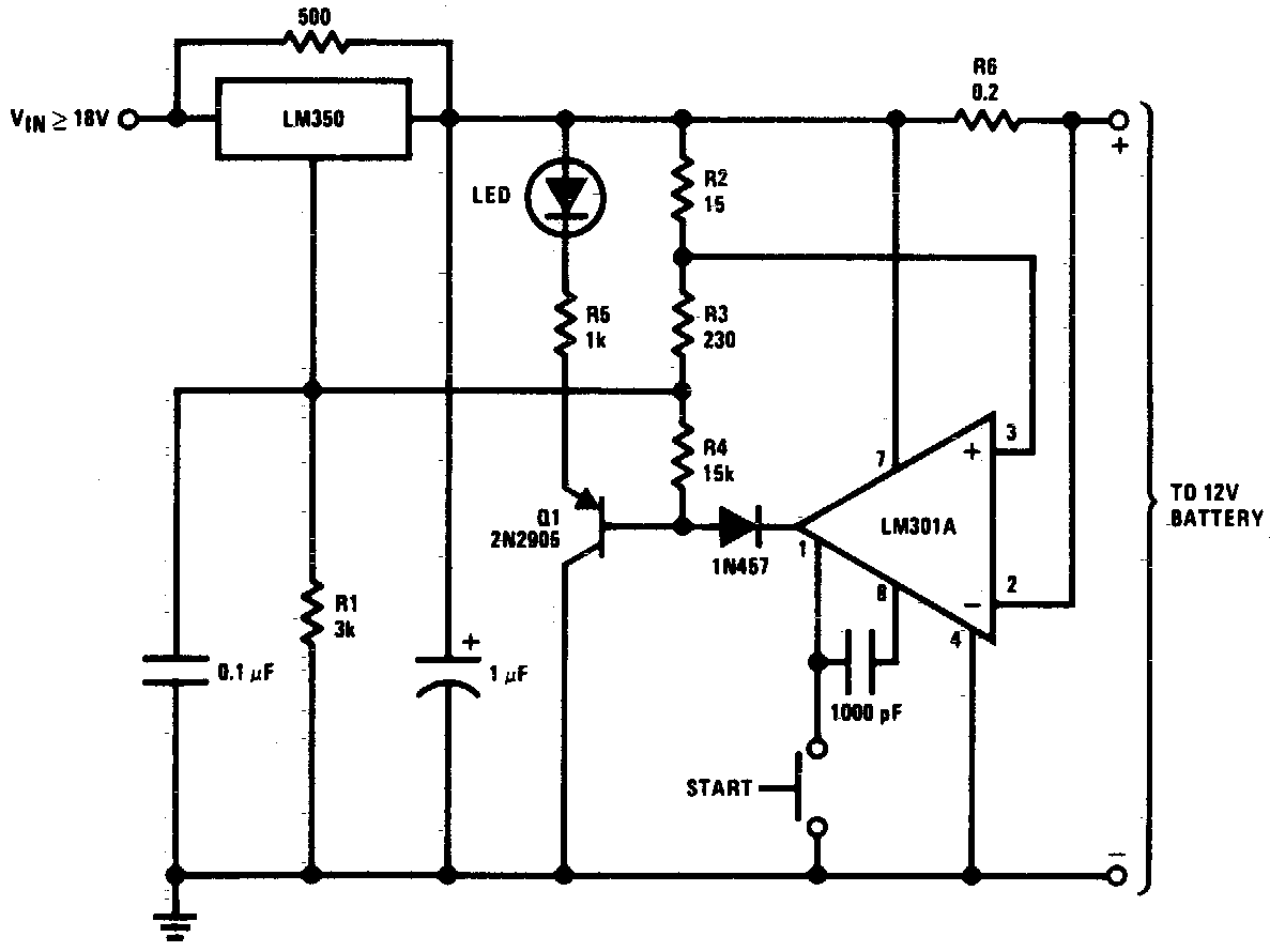
DC 12V Battery Charger Circuit Diagram. This circuit is a high-performance charger for gelled electrolyte lead-acid batteries. The DC 12V battery charger circuit is designed to efficiently charge gelled electrolyte lead-acid batteries, which are commonly used in various applications due...