
DIY siren project
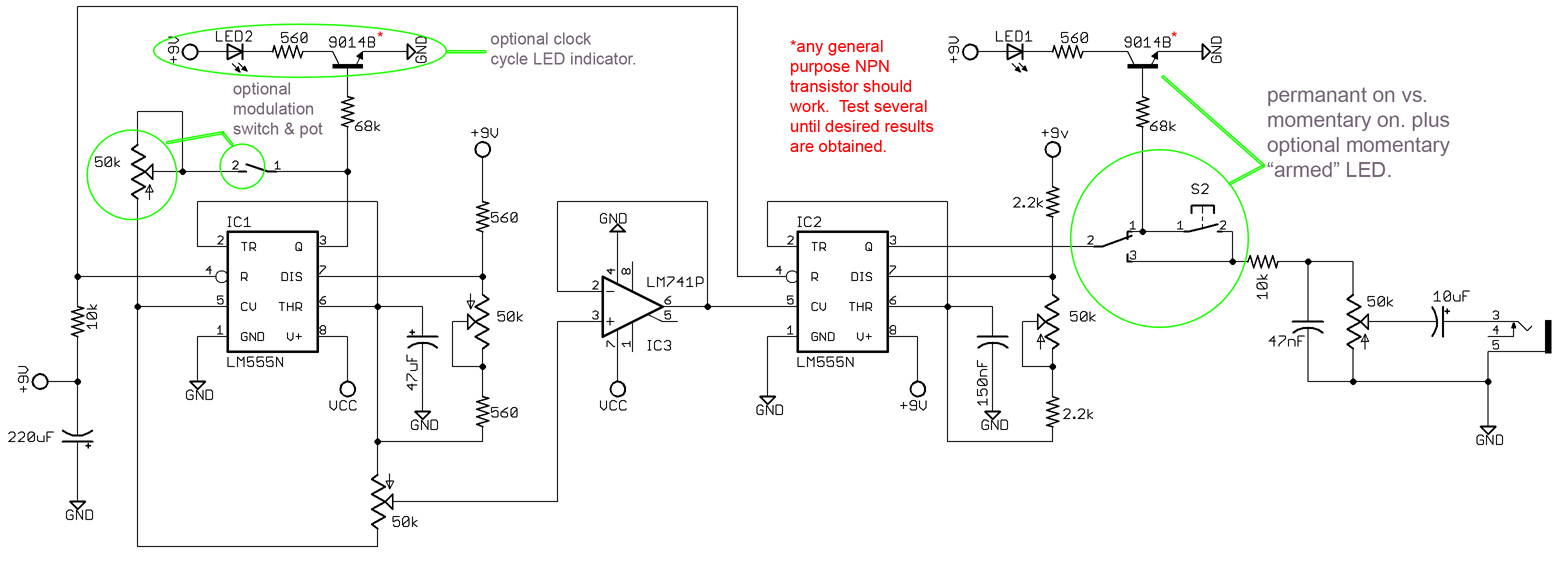
In this DC circuit, it is essential to ensure proper connections for the positive (+) and negative (-) wires to facilitate correct operation. The positive terminal of the power supply, typically a 9V battery, connects to all points marked +9V on the schematic, which are designed to share the same voltage level. The Vcc connections, which are synonymous with the power source, also tie into these +9V points, ensuring a consistent voltage supply throughout the circuit.
Ground connections are crucial for circuit stability and noise reduction. All ground points in the schematic should be interconnected and subsequently connected to the negative terminal of the power supply. This common ground reference is vital for the proper functioning of the circuit components, including the 555 timers.
The 555 timer circuits mentioned consist of a simple oscillator and a voltage-controlled oscillator, both of which are widely used in various applications due to their versatility and ease of implementation. The simple oscillator generates a square wave output, while the voltage-controlled oscillator modulates the frequency based on an input voltage, making them suitable for signal generation and modulation tasks.
Regarding the capacitor, it is important to note that the schematic specifies a polarized 10uF capacitor. The use of a ceramic capacitor, which is typically non-polarized, may not be appropriate in this context. A polarized capacitor is designed to allow current to flow in one direction, which is crucial in certain applications to prevent potential damage or malfunction. Therefore, acquiring a suitable polarized 10uF capacitor is recommended.
The 50k potentiometer serves as a volume control, allowing the user to adjust the output level from the circuit. The presence of the 10k resistor before the potentiometer creates a voltage divider, limiting the maximum output level. This design choice provides an additional layer of control over the output, allowing for customization based on user preference. Adjusting the value of the 10k resistor can further refine the maximum volume achievable, necessitating experimentation to determine the optimal configuration for the intended application.Since this is a DC circuit, how and where do the + vs. the - wires physically get connected to the circuit Where exactly do I connect all the grounds to I understand all the places where the schematic calls for a connection to the power source. I`m just having a hard time visualizing it. All 6 of the points labeled +9V tie together and go to The positive terminal of your 9V battery or power supply.
2 other points are labeled Vcc, They should also connect to those 6 points labeled +9V. Vcc is just another way of saying power source +. 555 circuits are easy mostly. The first is a simple oscillator, the second 555 is a voltage controlled oscillator. You want something simple, try one of these. Can someone please help again. I am working on the +output where it calls for a 10uF capacitor shown on the schematic from my first post. I have a 10uF capacitor, but it is ceramic and it does not show any polarisation on the actual capacitor.
Do I need a different capacitor Or will this one work The schematic obviously calls for a polarised 10uF cap. The 50k pot ahead of that cap is the volume control. It goes from zero to almost max available output. It`s almost max because the 10k resistor ahead of the pot forms a voltage divider with the pot so you don`t quite get full output.
If you still want to limit the maximum volume, increase the value of that 10k resistor. You`ll have to experiment to find the volume you like. 🔗 External reference
Related Circuits
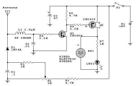
This electronic RF detector project is designed using common transistors and a few standard electronic components. The RF detector responds to RF signals below the standard broadcast band and well over 500 MHz, providing both visual and audible indications...
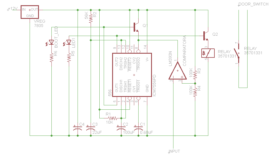
This button, with some modifications, allows the opening of an office door using Nexus One, iPhone, or SMS. Positioned near the reception desk, this button activates an electronic latch on the front door. Upon removing the assembly from the...
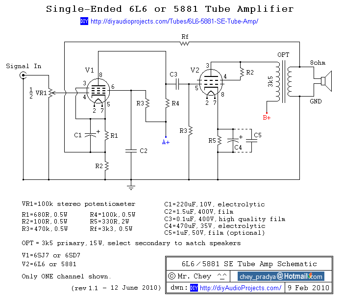
This past summer, an inspiration arose from watching "Transformers: Revenge of the Fallen" to construct an enclosure for a vacuum tube amplifier featuring the Decepticon logo. The tube amplifier replaces a solid-state amplifier that was driven by a tube...
After completing several V-USB tutorials, the next project undertaken was to create a compact USB HID keyboard device that types a password stored in EEPROM each time it is connected. The password can be regenerated by pressing the CAPS...
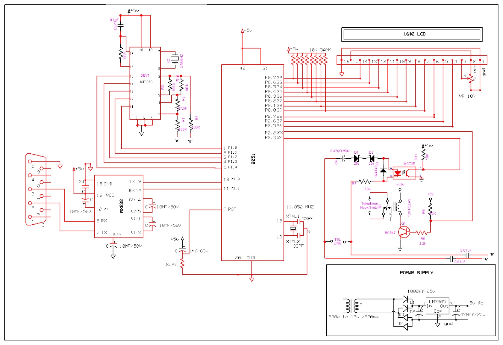
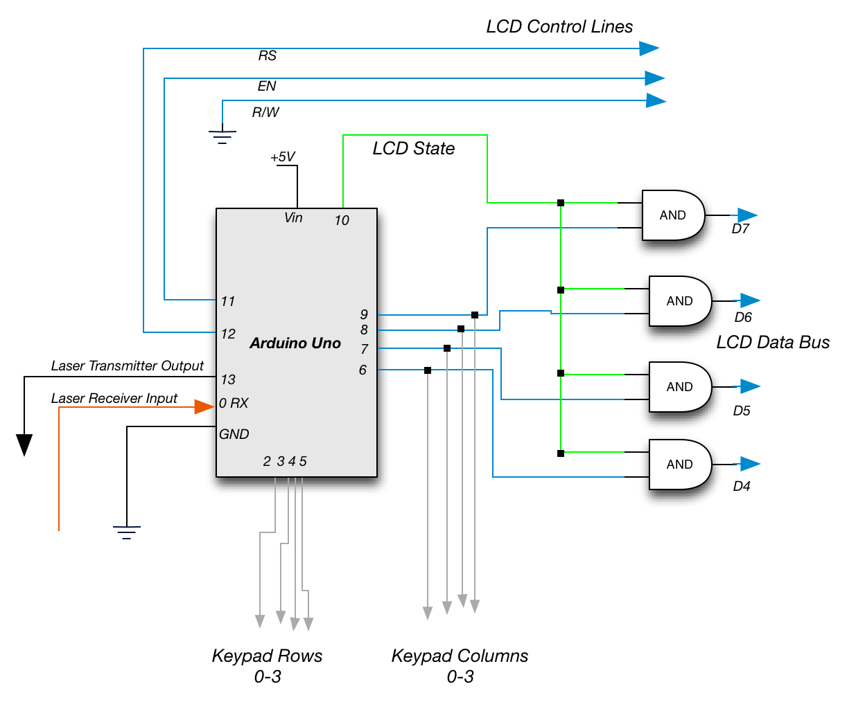
An Interactive Voice Response (IVR) system is a communication system that enables automated telephone call access to specific computer database information. This technology allows a computer to detect DTMF (Dual-tone multi-frequency) keypad inputs and generate voice responses based on...
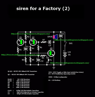
This is a powerful siren circuit diagram. This circuit can provide significant support for alarm systems, enabling users to achieve optimal results. The siren circuit is designed to produce a loud sound for alerting purposes, commonly used in security systems,...