
door opener science project

The electronic circuit described involves a simple push-button mechanism that operates an electronic latch to secure or release a door lock. The system is designed for low-voltage operation, ensuring safety and ease of integration into existing infrastructure. The button is connected to two wires that form the core of the electronic latch mechanism, which can be activated remotely through networked devices.
The choice of the Linksys WRT54GL router for this project is significant due to its support for open-source firmware such as OpenWRT. This firmware provides the necessary flexibility to customize the router's functionality to meet specific project requirements. The installation of a lightweight version of Python allows for scripting capabilities, enabling the control of GPIOs through network commands. The GPIOs serve as digital inputs and outputs, facilitating the interaction between the router and external components, such as the push-button switch and the electronic latch.
The addition of a pin header to the router's PCB is a practical modification that enhances the router's capability to interface with other electronic components. This modification allows for easy access to the GPIOs, enabling the integration of various sensors, actuators, or other devices that may be required for expanded functionality.
Overall, the project exemplifies the integration of consumer-grade electronics with custom firmware and scripting to create a network-enabled door access control system. The combination of low-voltage operation, programmable GPIOs, and the ability to control the system remotely through a network connection creates a robust solution for modern office environments.This button, with a few hacks, now makes it so we can open up our office with our Nexus Ones, iPhones or even SMS. Located near the reception desk, this button opens an electronic latch on the front door. Pulling the assembly out of the wall revealed the system to be about as simple as possible: the button simply connects two wires.
Bridging them with a screwdriver fired the latch (from their small gauge and uninsulated connections, it was obvious we weren`t dealing with dangerous voltages, but please don`t start pulling cable from your walls unless you know what you`re doing). Connecting two low-voltage wires electronically isn`t a particularly hard trick, so I decided it`d be fun to spend some evenings building a system to expose that switch to our network.
I`ve built a few projects in the past that make use of custom router firmwares and Arduino microcontrollers, so I decided to use those tools for the job. I`m a big fan of this approach - it`s a great, inexpensive way to add a scriptable network interface to your microcontroller projects (if you`re interested, I talk more about this technique here ).
Ultimately, I ran into difficulty getting this particular router`s serial connection to work, so I abandoned the Arduino - it was overkill anyway. Inspired by the excellent new MAKE: Electronics book, I decided to build a circuit to do the job. Here`s the finished franken-router, hooked up to the switch: So how does this all work Well, let`s start with the router.
It`s a Linksys WRT54GL, a still-Linux-friendly descendant of the WRT54G, the router which jump-started the custom firmware scene. There are a lot of custom router firmwares available - DD-WRT, Tomato, Gargoyle - and they can all make your consumer-grade router do some professional-grade things.
For this project I used OpenWRT, the system on which many of those other projects are based. It`s got a much steeper learning curve than those other distros - you definitely need to be comfortable with the command line - but it lets you build a custom firmware with exactly the components you want. With some tweaking I was able to create a firmware that included a stripped-down version of Python, but which still fit into the WRT54GL`s meager 2MB flash memory.
(Like the Arduino, Python turned out to be overkill, but at the time I expected to need it - and it`s always nice to have it handy. ) With the firmware installed, I was able to SSH into the router and perform some simple manipulations of the system`s GPIOs - General Purpose Input/Outputs.
These connect to things like the system`s LEDs and switches, and can be controlled in software. I selected a GPIO that didn`t seem to be used by OpenWRT - it illuminates the "DMZ" LED on the front panel - and wrote a very simple script to control it. I could now flip a tiny light on and off from a network connection. The hard part was over. Next came the hardware. It was easy to add a pin header to the router`s PCB - it`s got holes drilled and ready to go (some of them are connected to router systems - see here ).
To this I hooked up ground, 🔗 External reference
Related Circuits
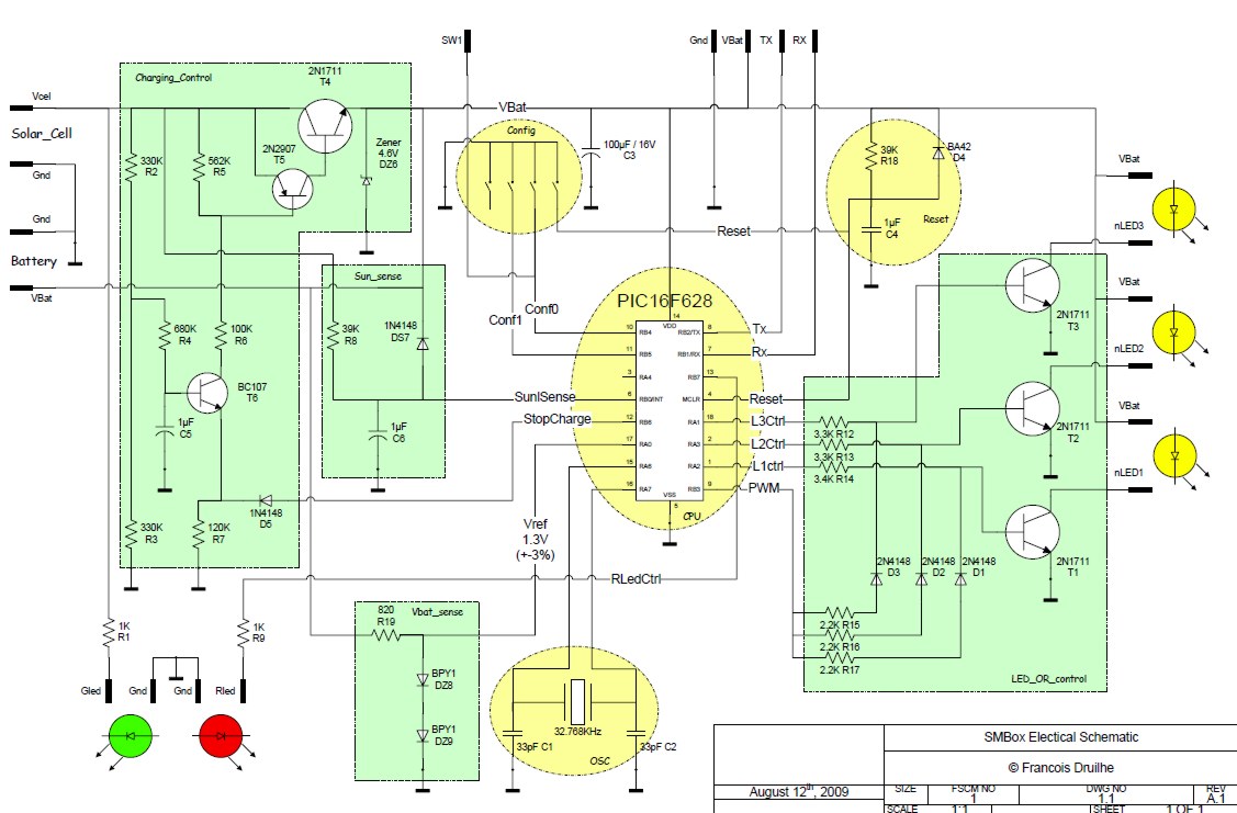
The objective of this project is to create a self-sustaining mailbox that operates solely on solar power and displays the house number based on the battery level. The system is designed to function autonomously, regardless of light conditions for...

This lie detector circuit provides two readings: one for difficult questions and another for the subject's general emotional state. Two flexible, uninsulated wires wrapped around the fingers or wrist can serve as electrodes. Each change in resistance, and consequently...

This simple electronics timing light uses an RC circuit as a delay-off timer to control an incandescent lamp via a relay. The described timing light circuit employs a resistor-capacitor (RC) network to create a time delay that governs the operation...
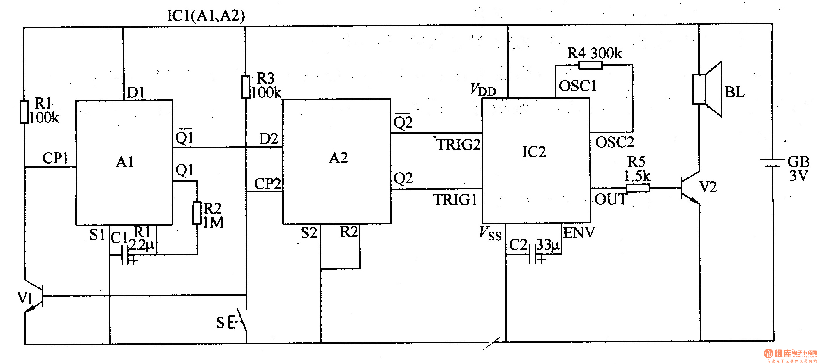
The two-tone electronic doorbell circuit consists of an input trigger circuit and an audio output circuit. The input trigger circuit includes a doorbell button (S), a transistor (V1), resistors (R1-R3), a capacitor (C1), and a dual D flip-flop integrated...

When the switch SI is pressed, a positive voltage is applied to capacitor C2 and the non-inverting terminal of operational amplifier U1. The circuit oscillates at a low frequency initially. As capacitor C2 charges through resistor R3, there is...

The following circuit illustrates the Ford Probe Single Wire Door Alarm System. This Single Door Locking Wire manages both LOCK and UNLOCK functions, indicating that the pulse wires must be connected to the same vehicle wire. The system primarily...