
rf detector electronic project circuit design using 2n2222 transistors

This RF detector circuit utilizes a straightforward design that leverages common electronic components, making it accessible for hobbyists and engineers alike. The primary function of the circuit is to detect radio frequency signals across a broad frequency range, from below the standard AM broadcast band to frequencies exceeding 500 MHz. The inclusion of both visual and audible indicators enhances usability, allowing users to easily identify the presence of RF signals.
The circuit's sensitivity can be adjusted through the biasing of diode D2 via the potentiometer R2, enabling the detection of varying signal strengths. This versatility is particularly useful in applications where the RF signal may vary significantly in power. The power supply requirements are minimal, as the circuit operates effectively with a 9-volt battery or a similar DC power source, ensuring portability and ease of use.
For enhanced performance, particularly in environments with weak RF signals, the addition of a wideband RF amplifier is recommended. This amplifier should be connected between the antenna and the detector diode, which will significantly improve the circuit's sensitivity. Careful attention to the physical layout of the circuit is crucial; keeping the leads of the diode and capacitor (C1) short helps to reduce stray inductance, which can adversely affect performance and accuracy.
The choice of transistors is also important for optimizing the circuit's performance. The PNP transistors, such as the 2N3906 or 2N2907, are suitable for Q2, while NPN transistors like the PN2222A or 2N3904 serve well for Q1. These transistors are known for their high gain characteristics, which are essential for amplifying weak RF signals effectively. Overall, this RF detector circuit exemplifies a practical and efficient design suitable for a variety of RF detection applications.This electronic rf detector electronic project is designed using common transistors and other few common electronic parts. This rf detector responds to RF signals bellow the standard broadcast band to well over 500 MHz and provides an visual, and audible indication when the signal is received.
By adjusting the bias of D2 with the R2 potentiomete r the circuit can detect low power or strong signals. The circuit can be powered using a simple 9 volts battery or any other 9 volts DC power supply circuit. If the rf detector is not enough sensitive you can connect a good wideband RF amp between the antenna and the detector diode.
Keep diode and capacitor (C1) leads short to minimize stray inductance. The used transistors can be : 2N3906, 2N2907 or other PNP high gain transistor for Q2 and PN2222A, 2N3904 or other NPN high gain transistor for Q1. 🔗 External reference
Related Circuits
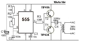
This 12V power inverter circuit can be utilized to power small devices that require 240 volts. It is particularly advantageous for operating 240-volt appliances using a 12-volt car battery. Unlike typical feedback oscillator inverters, this design employs a 555...

When the input voltage is between 198-242V, the average load current should be maintained at 0.5-1A, and the output voltage must remain at 15V with an error margin of less than 5%. The design and measurement of the stabilized...

Wireless FM Transmitter. The site provides some explanation on how the circuit operates; however, there are uncertainties regarding certain components, including the electret microphone and the frequency modulation process. The electret microphone operates at a current of 200 µA,...

The term amplifier, as used in this article, can refer to either a circuit (or stage) utilizing a single active device or a complete system such as a packaged audio hi-fi amplifier. An electronic amplifier is a device designed...

To ensure proper operation of the transistor in a circuit, it is essential to measure the reverse breakdown voltage of the transistor. This is particularly important for tubes with high reverse breakdown voltage requirements, such as those used in...
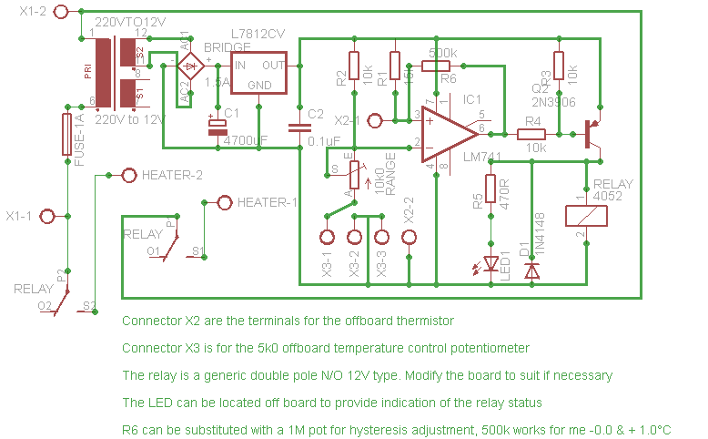
Affordable, straightforward, and precise thermostat circuits with instructions. The thermostat circuit is designed to provide a cost-effective and reliable solution for temperature control applications. It typically utilizes a temperature sensor, such as a thermistor or a thermocouple, to monitor the...