
PIC16F628 2 Input Alarm Circuit
The two-input alarm circuit designed with the PIC16F628 microcontroller leverages the internal 4 MHz oscillator to provide a stable clock signal for operation. This microcontroller features multiple I/O pins that can be configured for digital input or output, making it suitable for sensing alarm conditions from two separate inputs.
In this circuit, the two inputs could be connected to various sensors, such as motion detectors, door switches, or temperature sensors. The microcontroller continuously monitors the status of these inputs. When a condition is detected—such as a door opening or motion being sensed—the microcontroller processes the input signal and triggers an alarm response.
The alarm response could include activating an audible alarm, illuminating an LED, or sending a notification signal to another device. The internal oscillator ensures that the timing of these operations is precise, allowing for reliable detection and response to alarm conditions.
The circuit can be designed with additional features such as debounce logic for mechanical switches, ensuring that false alarms are minimized due to noise or bouncing contacts. Furthermore, the use of pull-up or pull-down resistors may be implemented to stabilize the input signals.
Power supply considerations are also essential, as the circuit must operate within the voltage specifications of the PIC16F628, typically between 2.0V and 5.5V. Proper bypass capacitors should be included to filter any power supply noise that could affect the microcontroller's performance.
Overall, the integration of the PIC16F628 with its internal oscillator in a two-input alarm circuit provides a versatile and effective solution for security and monitoring applications.The program uses the internal 4MHz oscillator PIC16F628 2 Input Alarm Circuit.. 🔗 External reference
Related Circuits

This is a transistor inverter circuit diagram rated for 100 watts, designed as an easy-to-build circuit. It utilizes only transistors and does not incorporate any integrated circuits. The circuit converts a 12V battery input to a 220V, 50Hz square...
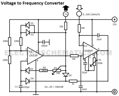
This voltage-to-frequency converter circuit features a voltage-controlled oscillator with a small deviation of 0.5%. The integrated circuit IC1 operates as a multivibrator. The voltage-to-frequency converter circuit is designed to convert an input voltage into a corresponding frequency output. The core...

This circuit is designed to drive an ultrasonic transducer. A question has arisen regarding how to limit the output current, as a 60W transducer may be at risk of damage due to excessive current. Guidance or examples for integrating...

The alarm/sensor circuit is constructed using two SCRs, a transistor, a 4049 hex inverter, and several supporting components, which together create a closed-loop detection circuit featuring a delay mechanism. This delay allows entry into a protected area and deactivation...

The 555 limit circuit, which is an integrated electrical circuit, is designed to manage large electrical loads. It automatically disconnects power when the load exceeds a predetermined threshold. Once the load is reduced below this threshold, power is restored...
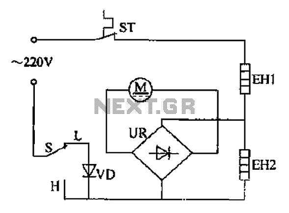
The comb electric circuit illustrated in Figure 1-3 features two temperature settings. By toggling switch S to either the L or H position, different temperatures can be achieved. Once switch S is activated, the circuit powers the heating wires...
Warning: include(partials/cookie-banner.php): Failed to open stream: Permission denied in /var/www/html/nextgr/view-circuit.php on line 713
Warning: include(): Failed opening 'partials/cookie-banner.php' for inclusion (include_path='.:/usr/share/php') in /var/www/html/nextgr/view-circuit.php on line 713