
Preamp Protection
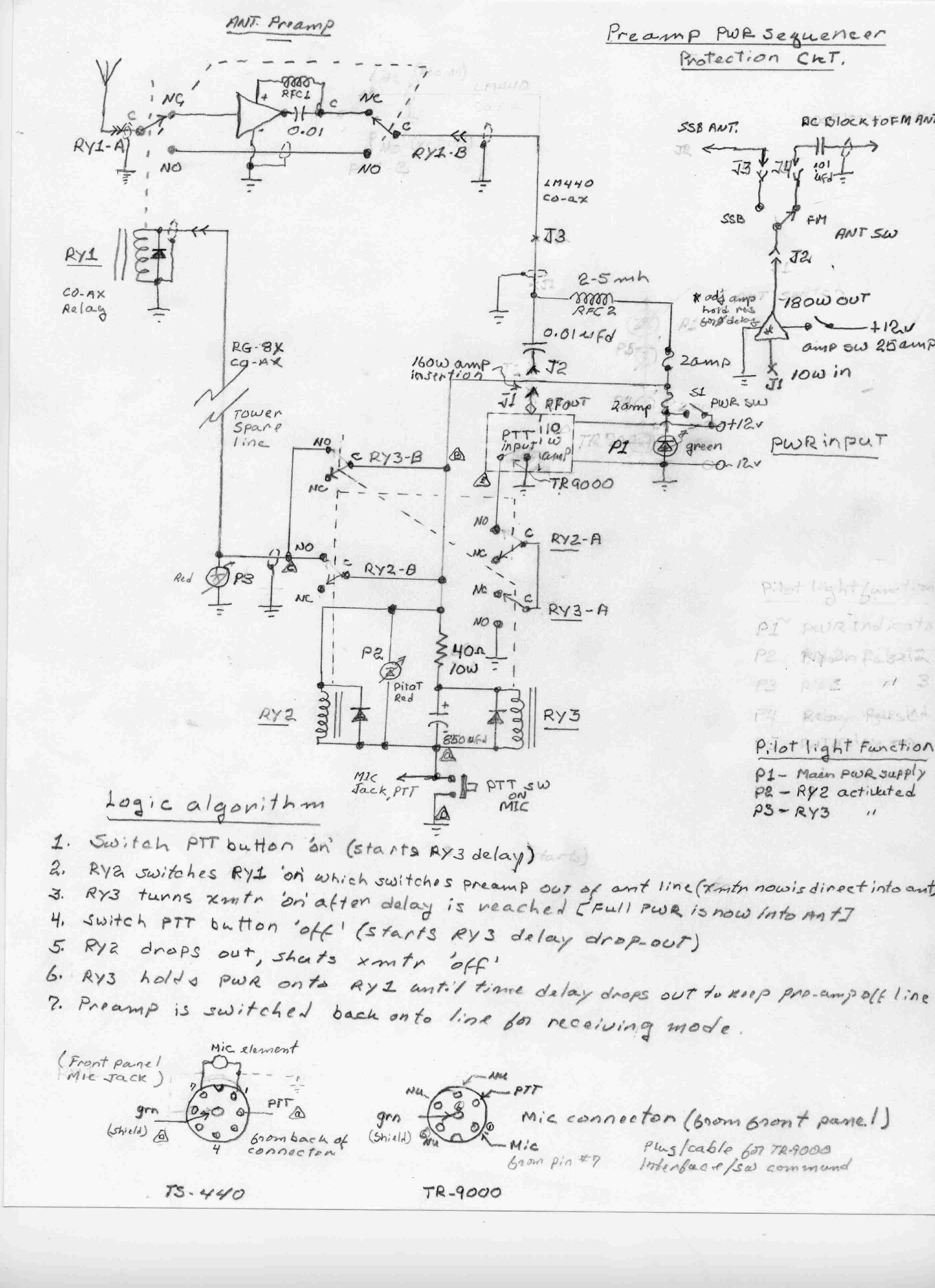
The design of the power sequencer incorporates several key components and considerations to ensure reliable operation. The circuit utilizes relays to create a timing mechanism that effectively disconnects the pre-amplifier during transmission. The relays are activated in a sequence to manage the power flow, ensuring that the pre-amplifier is offline when the transmitter is active, thus preventing damage from high power levels. The timing circuit is designed to minimize the risk of electrical spikes, which can occur when relays are switched, by incorporating flyback diodes across the relay coils. This suppression technique protects sensitive components from voltage transients that might otherwise cause failure.
In terms of the schematic, the power sequencer includes a control circuit that monitors the transmitter's operation. This could involve a simple RF sensing circuit that detects the presence of RF signals and triggers the relays accordingly. The relays themselves should be rated for the power levels expected in the system and should be chosen for their reliability and speed of operation. The design may also include LED indicators to provide visual feedback on the status of the relays and the overall system operation.
The integration of the pre-amplifier into the antenna system is critical for enhancing the receiver's performance. The pre-amplifier should be selected based on its gain characteristics and noise figure, ensuring that it provides the necessary amplification without introducing excessive noise. The placement of the pre-amplifier at the antenna feed point is advantageous as it minimizes losses in the coaxial cable, which can degrade signal quality.
Overall, this power sequencer design represents a practical solution for amateur radio operators seeking to improve their two-meter SSB operations while maintaining the integrity of their equipment. By carefully considering the components, timing, and protective measures, a robust system can be created that enhances performance and reliability.While working two-meter SSB from the Benson area, I decided that local terrain and the limited height of my home-made six-element yagi, necessitate I incorporate a high gain antenna pre-amplifier at it`s terminations to enhance receiver signal strength. This approach would give that little extra advantage to help dig the signals out of the noise levels.
I knew that this method would produce superior results, compared to a pre-amp located close to the transmitter at the other end of the transmission line. Unfortunately, this approach requires that the pre-amp be protected from the high power being fed from the finals in the transmitter to the yagi.
In my case it was a 160 watt output `brick` driven from a Kenwood TR-9000 all mode transceiver. Consequently, the pre-amp needs to be switched out of the line during SSB transmission. There are a number of schemes/approaches for doing this task. The most common uses an rf switch (senses minute amounts of rf during initiation of the transmission phases and activates a relay to place the pre-amp off line). Unfortunately, there are many examples of failure using this technique to really protect the pre-amps reliably.
Case in point. many `brick-amp/pre-amp` combos available to the ham community suffer from blown pre-amps. There are some expensive sophisticated power management/switching devices available, but again cost can be a factor incorporating them into the average `Joe`s` ham shack budget. I conducted a detailed search on the net for a low cost approach, and couldn`t find a suitable project, thus the unit which I came-up for my needs is presented herein.
As with all prudent projects, the old scrap/salvage box becomes a key player in the design, and this endeavor is no exception. My approach to make a simple timing circuit uses relays. I call this strategy my `cave-man mentality design approach` although using relays for timing applications has been around for a long time, they are fairly plentiful, relatively inexpensive and reliable.
However, one must take into account they can generate killer-electrical spikes if not suppressed with diodes (bad for the poor-little pre-amp). Also relay contact bounce must be accounted for if used for more critical timed switching applications.
With all this rational used in the design-approach behind us, lets review the schematic of the finished `power sequencer`. This design was tailored for my equipment, which integrated the HF rig (In this case my TS-440 HF transceiver) a multi antenna systems, with a single mic shared between several transmitters.
If you don`t need these amenities, they may be eliminated for your specific requirements to simplify my gadget further. One last note. . . when using the add-on brick power amps, most of these devices can extend SSB hang/hold-on periods for 2-3 seconds after the mic key is released.
You should adjust this for less than a half second maximum hold delay, or else you will defeat the power-sequencer pre-amp protection scheme. After assembling your unit, recheck, recheck and recheck again to ensure that the relay sequence periods and pattern is correct for your particular application before applying transmitter power to the system.
I used a dipole driven element for my yagi. If yours is anything other than that, use an additional d. c. blocking capacitor so the 12 volt power source isn`t shorted, if warranted I found this project to significantly enhance signal to noise ratio, compared to the pre-amp located in the `brick` high power amplifier. With that, good luck on your project. I`ve rechecked the schematic several times to ensure that all the changes/corrections have been added.
Hopefully I caught everything. However, if I missed something or you want to discuss this further, email me at vanaglash@msn. com. 🔗 External reference
Related Circuits
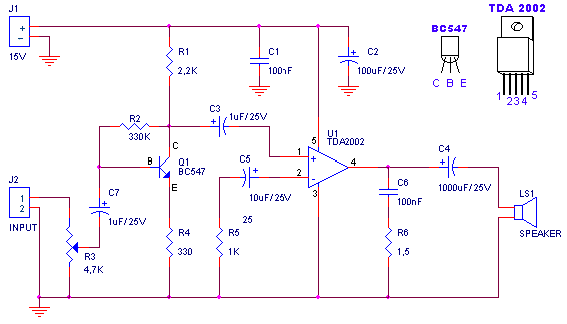
A small amplifier with nice characteristics: Tendency of catering: 15V. Force of expense: 4.2Wrms in the 4W. Minimal signal of entry: 94mVp-p with preamplifier, 0.65Vp-p without the preamplifier. More: Materially: R1=2.2kΩ R2=330kΩ R3=4.7kΩ logarithmic potentiometer R4=330Ω R5=1kΩ R6=1.5Ω C1,...
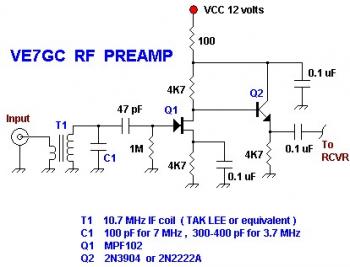
This is a simple VE7GC Popcorn RF preamplifier designed by Dick Pattinson. The circuit features a single tuned circuit at the input stage, allowing direct connection to a mixer or product detector in a straightforward receiver project. Adjustable RF...
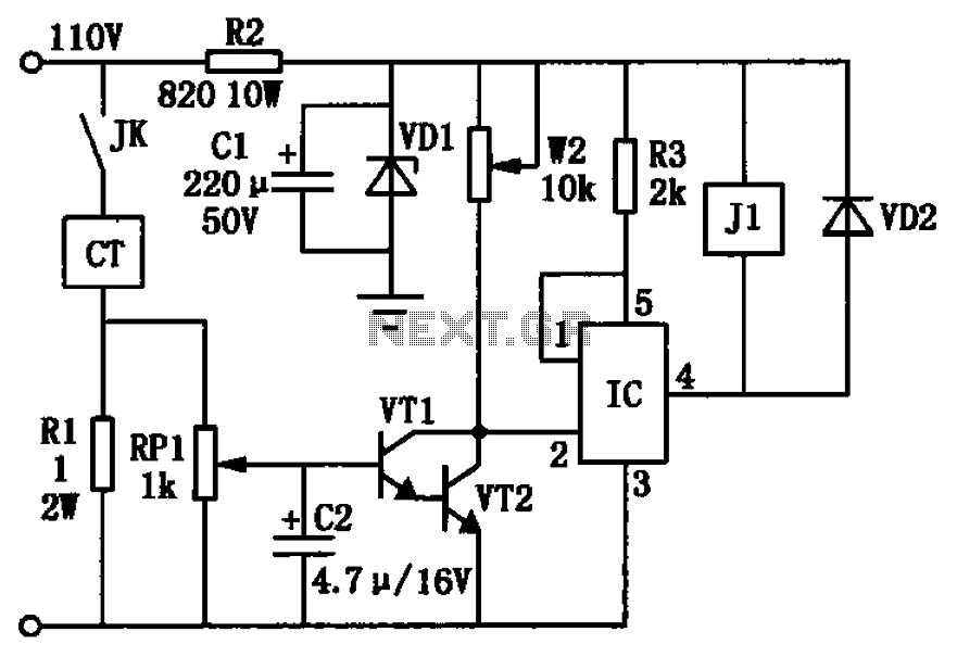
The circuit depicted in the figure utilizes a +24V power supply derived from a 110V power source through an electromagnetic chuck. When the electromagnetic chuck circuit is activated, the contact JK closes, enabling the operation of the magnetic chuck....
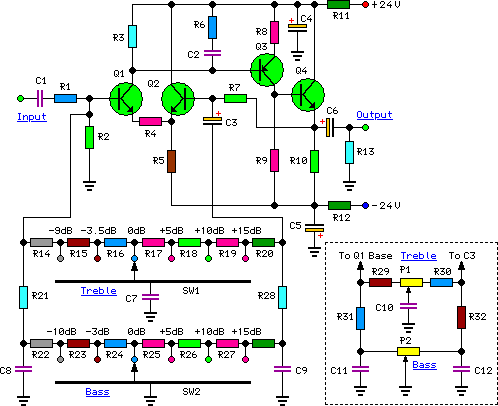
High-quality, discrete component design for input and tone control modules to complement the 60-watt MOSFET audio amplifier with a high-quality preamplifier design. The circuit design focuses on creating a high-fidelity audio preamplifier that enhances the performance of a 60-watt MOSFET...
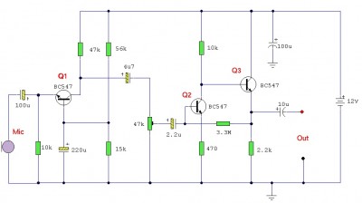
This is an audio preamplifier for dynamic microphones with an output impedance of 200-600 ohms and a low-noise pre-amplifier ideal for signal strengthening. It features a three-stage discrete amplifier with gain control. Transistor alternatives such as BC109C, BC548, BC549,...
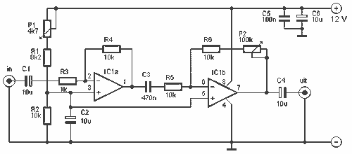
This is a good example preamplifier for microphones that can be used in mixing consoles. The circuit uses a dual op-amp, type NE 5532. The amplifier must be adjusted. This connect the power supply and control over P1 such...