
DIY video dolly stepper motor driver
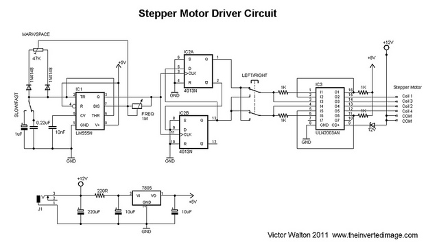
The circuit utilizes a 555 timer in astable mode to generate a pulse-width modulation (PWM) signal, which controls the timing of the stepper motor's operation. The variable mark/space ratio allows for precise control over the speed of the motor by adjusting the duty cycle of the PWM signal. The D-type flip-flops (4013) are utilized to create a binary count sequence, which is essential for driving the ULN2003 stepper motor driver. The ULN2003, a high-voltage, high-current Darlington driver, is specifically designed to control inductive loads such as stepper motors.
The DPDT switch plays a crucial role in the direction control of the stepper motor. By reversing the connections, the switch allows the motor to rotate in either direction, providing flexibility in operation. The dual coil drive configuration of the ULN2003 ensures that the unipolar stepper motor receives adequate power, enhancing its torque and performance, particularly when moving heavier loads like a dolly.
The 7805 voltage regulator is essential for providing a stable 5V supply to the digital components, ensuring reliable operation of the 555 timer and flip-flops. The choice of timing capacitors, including the tantalum and mylar types, is critical for maintaining the stability of the 555 timer's output, which directly influences the performance of the entire circuit.
In summary, this circuit design effectively combines a 555 timer, D-type flip-flops, and a ULN2003 driver to create a robust stepper motor control system suitable for applications such as camera dolly systems. Future iterations could explore additional features, such as half-step driving with a decade counter, to further enhance control and functionality.The ubiquitous 555 timer, (hooked up for variable mark/space ratio, if you build one you`ll find out why it`s needed), and a couple of D type flip-flops, (4013), to provide the count for the ULN2003 stepper motor driver. (ULN2003`s might be hard to find off the parts shelf nowadays, this one was stripped from an old printer board but a ULN2803 or
similar will do a nice job). The 4013 provides a 0011 and 0110 count required for the boot-strapped ULN2003, a DPDT switch providing forward and backward drive, (by simpling reversing the connections). The ULN2003 is hooked up in such a way as to provide dual coil drive for a unipolar stepper motor so that it gains more torque to drive the `dolly`.
A 7805 regulator to provide 5 volts for the 555 timer and flip flop, (the stability of the 555 timer is much improved by doing this!), and the 12 volt from the battery pack driving the stepper motor. The timing capacitors on the 555 are a tantulum, (1uF), and myler, (0. 22uF), types to further aid stability. Could it be better Yes, definately. I was going to use a 4017 decade counter hooked up with diode logic to provide half step driving to the stepper motor with a further output to fire the camera when the rail is not moving, but the scrap 4017 counter I lifted from a scrap board had a faulty output so that idea was put to one side.
Who knows, maybe I`ll get into this and put something more luxurious together. Or maybe not and I wouldn`t have wasted too much time and definitely no money. Nice.
Related Circuits
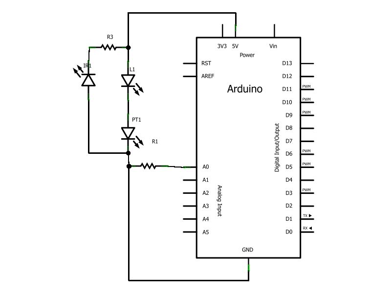
Have you ever wanted to create a line-following robot but found infrared sensors too expensive? If you are located in the UK and have access to a Maplin store nearby, you can purchase infrared transmitters and receivers for just...
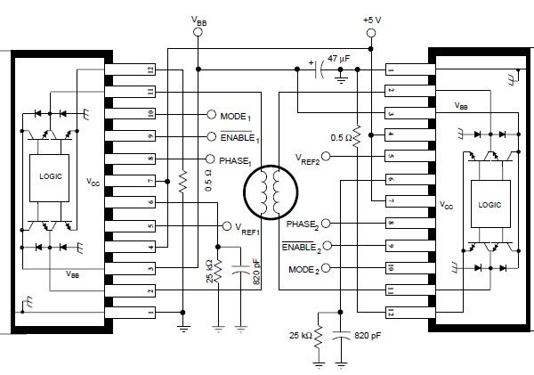
The A3952S stepper motor controller, designed by Allegro MicroSystems, can be utilized to create a straightforward and effective motor driver circuit suitable for various electronic applications. This controller supports continuous output currents of up to 2 A and operates...
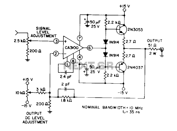
This circuit utilizes a wideband, high slew rate CA3100 BiMOS operational amplifier. The slew rate for this amplifier is 28 V/µs. The output swing is 9 volts peak-to-peak into a terminated line, measured at the termination. The CA3100 BiMOS operational...
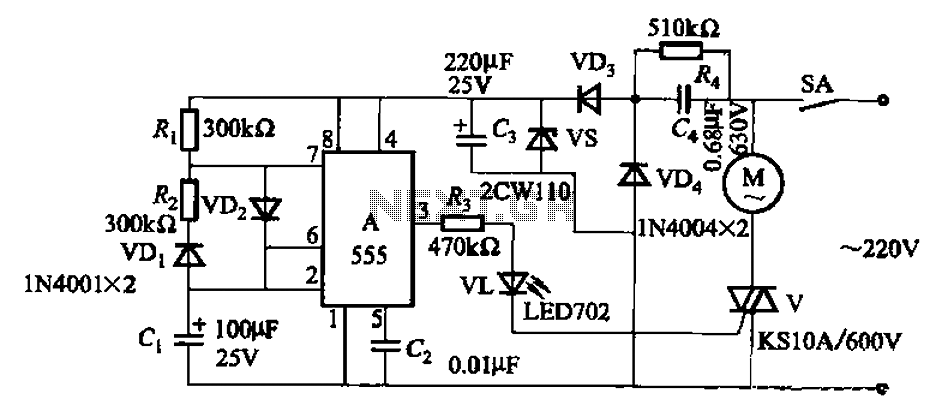
The circuit depicted in Figure 3-16 utilizes a 555 IC (Integrated Circuit) as the control element. It features a capacitive step-down circuit and incorporates a bidirectional thyristor (V) for intermittent motor control operation. By adjusting the resistance values of...
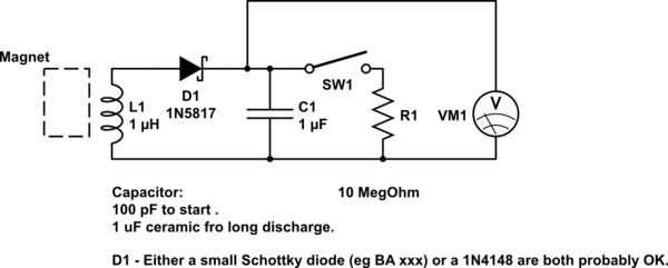
A DIY kinetic energy harvester utilizing the electromagnetic method to generate electricity. The materials that will be used are currently known. The project involves creating a kinetic energy harvester that converts mechanical energy from motion into electrical energy through electromagnetic...
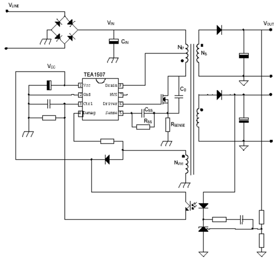
The power supply utilizing the TEA1507 driver is predominantly employed in Philips-branded televisions. This power supply achieves an efficiency rate of up to 90%, resulting in reduced cooling requirements and standby power consumption of less than 1 watt. The...