
A3952S stepper motor controller circuit design
The A3952S stepper motor controller is an integrated circuit designed to drive stepper motors efficiently and effectively. This device is particularly advantageous for applications requiring precise control of motor position and speed. The controller's ability to handle continuous output currents of up to 2 A makes it suitable for a variety of stepper motors, from small to medium-sized applications.
The internal fixed off-time PWM current control circuitry is a key feature, as it allows the user to set a maximum load current, which is crucial for protecting the motor and the driver from overheating and damage. The use of the MODE terminal provides flexibility in operation, enabling the selection of different modes for microstepping, which enhances the smoothness of motor operation and reduces vibrations.
In applications where the load current is subject to rapid changes, the implementation of slow-decay mode is beneficial. This mode helps in reducing the switching losses that occur during the operation of the motor, thereby improving overall efficiency. Additionally, the reduction of iron losses in the motor contributes to better performance and longevity of the motor.
For applications that demand high performance under heavy loads or continuous duty cycles, the thermal management of the A3952S is critical. By adding external diodes in parallel with the internal diodes, heat dissipation can be significantly improved. This is particularly important in high-current scenarios where excessive heat can lead to failure of the device. The recommendation to use only the top-side diodes for slow-decay applications simplifies the design while ensuring adequate thermal performance. Conversely, for fast-decay PWM applications, the inclusion of all four external diodes is essential to maintain optimal thermal conditions and prevent junction temperature from exceeding safe limits.
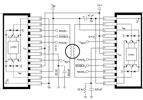
In summary, the A3952S stepper motor controller is a versatile and efficient solution for driving stepper motors in various electronic applications, providing features that enhance performance, efficiency, and thermal management.Using the A3952S stepper motor controller designed by Allegro MicroSystems can be designed a very simple and useful motor driver circuit that can be used in many electronic applications. A3952S stepper motor controller is capable of continuous output currents up to 2 A and operating voltages range up to 50 V.
Internal fixed off-time PWM current-c ontrol circuitry can be used to regulate the maximum load current to a desired value. The MODE terminal can be used to optimize the performance of the device in microstepping / sinusoidal stepper motor drive applications. When the average load current is increasing, slow-decay mode is used to limit the switching losses in the device and iron losses in the motor.
The thermal performance in applications with high load currents and/or high duty cycles can be improved by adding external diodes in parallel with the internal diodes. In internal PWM slow-decay applications, only the two top-side (flyback) diodes need be added. For internal fast-decay PWM, or external PHASE or ENABLE input PWM applications, all four external diodes should be added for maximum junction temperature reduction.
We aim to transmit more information by carrying articles. Please send us an E-mail to wanghuali@hqew. net within 15 days if we are involved in the problems of article content, copyright or other problems. We will delete it soon. 🔗 External reference
Related Circuits
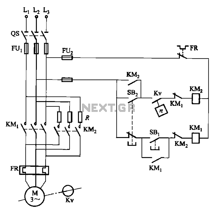
The circuit depicted in Figure 3-124 operates without an intermediate relay. Kv serves as the speed relay, activating when the electric motor speed exceeds 120 r/min while the contact is closed. If the speed drops below 100 r/min, the...
An adaptable siren generator circuit with multiple applications is presented. It is based on a 556 twin-timer chip, IC1. One timer section generates an audio tone that is directly coupled to the driver transistor, TR1. The other half of...
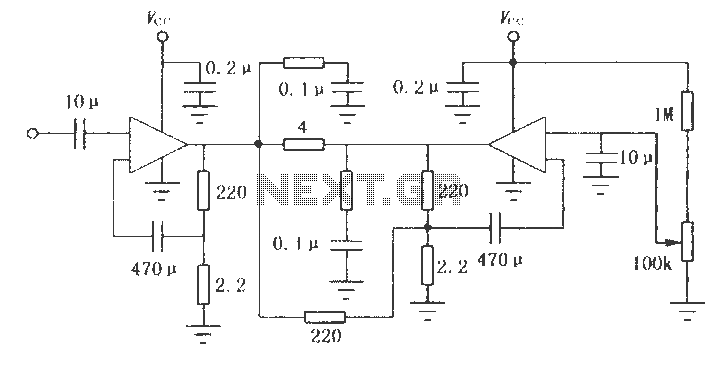
The LM2002 / 2002A is an audio power amplifier integrated circuit. The LM2002A features high voltage protection, with a maximum instantaneous power supply voltage of up to 40V, and comes in a 5-pin single in-line plastic package. This integrated...
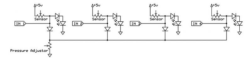
A dance pad consists of four pressure sensors (up, down, left, right). A USB controller has already been created for the dance pad, and the next step involves connecting the actual sensors. The intention is to pull the input...
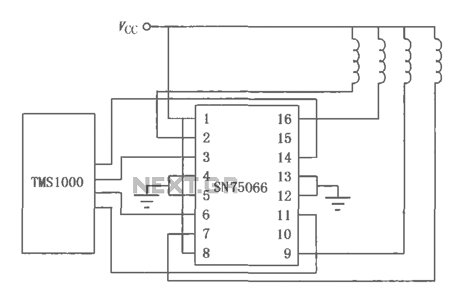
The SN75064 to SN75067 series consists of monolithic, high-voltage, high-current Darlington switch output terminations. These devices include clamp diodes, making them suitable for inductive loads. Each package contains four Darlington pairs that can be connected in parallel to achieve...
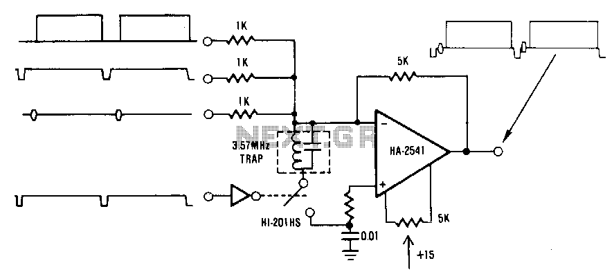
This circuit is a conventional summing amplifier configuration that incorporates a de-clamping circuit. The operation is straightforward; each component—synchronization, color burst, picture information, etc.—of the composite video signal is connected to its respective input terminal of the amplifier. These...