
Use TWH8751 street light control circuit
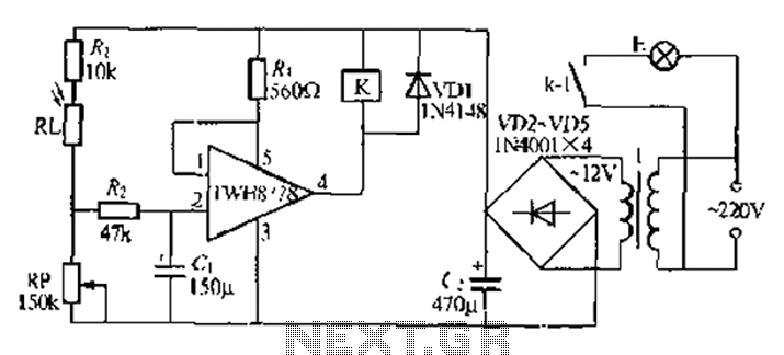
The automatic lighting circuit described integrates a light-sensitive control mechanism using the TWH87SL power switch integrated circuit. The primary function of this circuit is to automatically turn on lights in response to ambient light conditions. The TWH8751 input terminal receives power from a designated supply, and the operation of the circuit hinges on the relationship between the light sensor and the relay.
During daylight hours, the RP resistor's low resistance allows the strobe terminal to maintain a high state, which prevents the relay K from activating. This ensures that the lights remain off, conserving energy and enhancing safety by avoiding unnecessary illumination. Conversely, in low-light conditions, the RP resistor's resistance increases, resulting in a low signal at the strobe terminal. This triggers the TWH8751's internal Darlington transistor, which in turn activates relay K. The closure of relay K's contacts enables the flow of current to the lights E, illuminating the area as required.
The circuit's sensitivity to light can be finely tuned by adjusting the RP resistor, allowing for customization based on specific environmental conditions or user preferences. The inclusion of a pulse interference absorption circuit, consisting of resistors R and capacitors C, serves to filter out any transient signals that may cause false triggering of the relay due to fluctuations in ambient light levels.
Powering the circuit with a 220V AC supply necessitates the use of a compact, high-efficiency transformer rated at 121 jVA, which steps down the voltage to a manageable level for the relay and associated components. When selecting relay K, it is crucial to ensure compatibility with a 12V operating voltage, with options such as the JZ (22F, DC12V) relay being suitable for this application. This design offers a reliable and efficient solution for automatic lighting control in various settings, enhancing convenience and energy efficiency. Automatic lights using a light twist, it TWH87sl power switch integrated circuit composed of a first input terminal TWH8751 O feet to the positive terminal of the power supply, the output pin state by the end strobe terminal that is electrically feet first level control. During the day, RP by natural light exhibits low resistance, strobe terminal feet high, so the output terminal feet high, the relay K is not action, not bright lights E. Night, Rl. Light exposure exhibits high electrical resistance, strobe terminal feet low, TWH8751 internal Darlington turned, pin is low, the relay K pull its station close contacts kl, powered lights E light.
Adjusting the resistance of RP can adjust the sensitivity of the light control circuit. R., C. A pulse interference absorption circuit, can eliminate amidine nighttime light on the impact short circuit. T bite Chuan 220V: 121:, jVA small, high quality power transformer. K blood select the appropriate load size I according to operating voltage of 12V relay, such as JZ ( 22F, DC12V type.
Related Circuits
This project involves a simple touch switch circuit that can also be utilized to activate a relay instead of an LED and resistor. The circuit exhibits high sensitivity due to the use of two transistors configured as a Darlington...
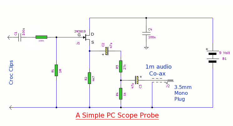
This simple PC scope probe functions as a FET follower, featuring high input impedance and low output impedance to match a microphone or line input socket on a PC or laptop. This design allows for practical examination of waveforms...
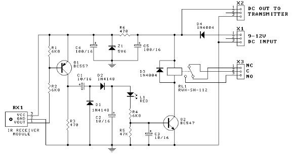
This door minder electronic project is based on a 555 timer circuit and utilizes an infrared (IR) beam to monitor doorways, passageways, or any other designated area. When the IR beam is interrupted, a relay is activated, which can...

This schematic diagram illustrates a single-chip Theremin circuit. A Theremin is an electronic musical instrument that detects hand movements to control tones and frequency. The circuit employs two separate Colpitts LC oscillators to generate a beat frequency. The frequencies...
This is a high-quality stabilized power supply circuit diagram. The output voltage can be adjusted from 0 volts to 30 volts DC, and the current output value can be adjusted from 0.002 A to 3 A. The circuit begins...
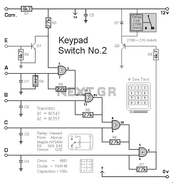
The Keypad Controlled Switch No2 Circuit operates with a 12-volt supply but is compatible with voltages ranging from 5 to 15 volts. The only requirement is to select a relay that matches the desired supply voltage. The Keypad Controlled Switch...