
Daytime driving lights schematic
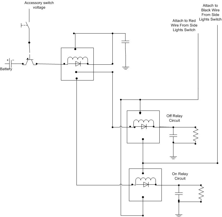
The installation of daytime driving lights (DRLs) enhances vehicle visibility during daylight hours, contributing to increased safety. In the case of the Elise, a compact sports car, integrating DRLs can be achieved through a straightforward circuit design.
The circuit can be constructed using a relay, which will allow the DRLs to be activated without the need for constant manual intervention. A typical setup involves connecting the DRLs to the vehicle's ignition system, ensuring that they turn on automatically when the engine is running.
The relay can be triggered by a 12V signal from the ignition switch. When the ignition is on, the relay closes, allowing current to flow to the DRLs. A fuse should be included in the circuit to protect against overcurrent conditions.
Additionally, a resistor may be used to limit the current to the DRLs, ensuring they operate within their specified voltage and current ratings. The connection points should be clearly marked to facilitate easy installation and maintenance.
For optimal performance, it is advisable to select LED DRLs due to their low power consumption and long lifespan. The physical mounting of the lights should be considered to ensure compliance with local regulations regarding their brightness and positioning.
Overall, this modification will provide a practical solution for maintaining the functionality of daytime driving lights in the Elise without the inconvenience of manual operation.Okay, I ve decided that I want Daytime Driving lights for my Elise. Also I don t want to keep pressing the button on and off each time I.. 🔗 External reference
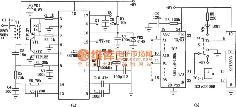
Related Circuits
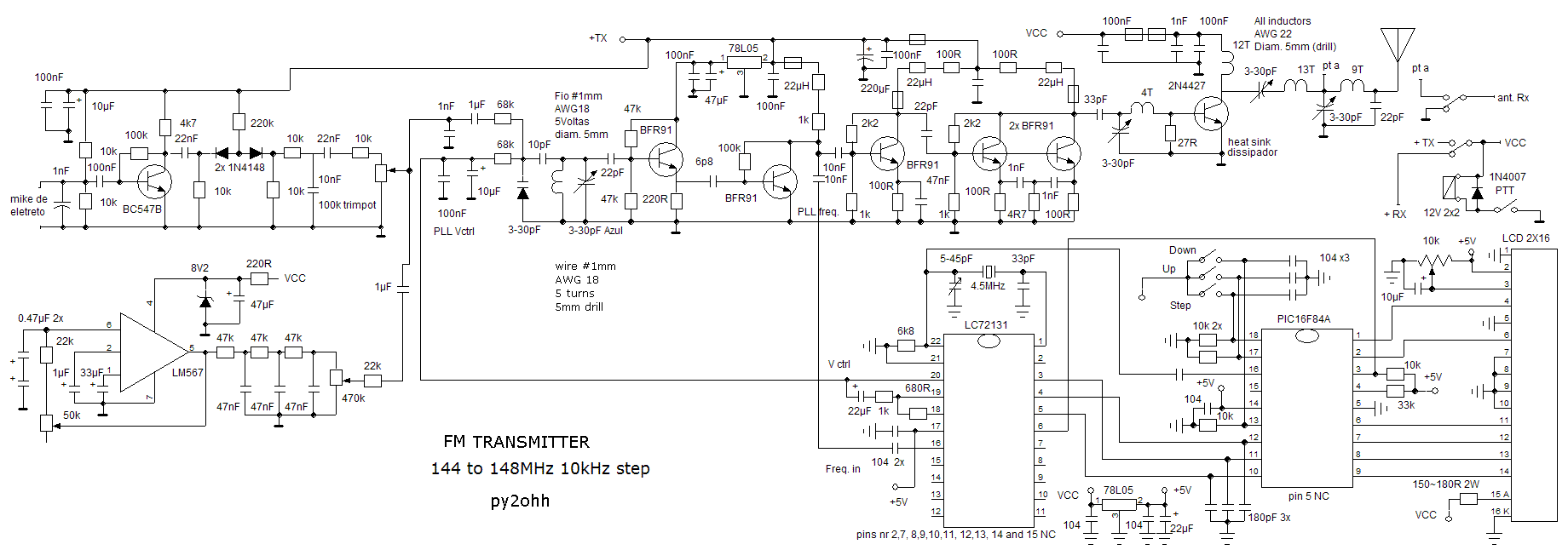
Another version of the 1W VHF amplifier for the FM transceiver is presented. It is essentially the same version since achieving 1W output power has not yet been realized. Recent tests were conducted using a 2N2553 and a 2N2866...
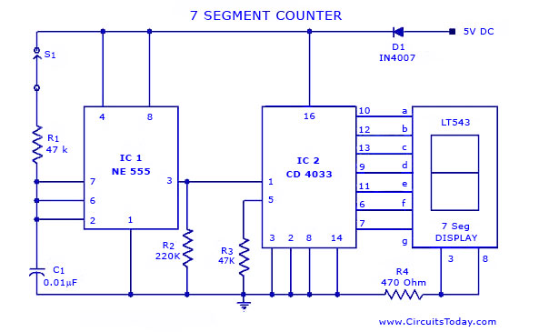
A simple seven-segment counter circuit with an LED display. This counter circuit diagram is designed using the IC CD 4033 as a counter, a 555 Timer IC, and a seven-segment LED display LT 543. The seven-segment counter circuit utilizes the...
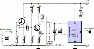
A popular project among microcontroller enthusiasts is to construct a radio-controlled clock. Compact receiver boards are available, equipped with a pre-tuned ferrite antenna, which can receive and demodulate the DCF77 time signal broadcast from Mainflingen, Germany. The DCF77 signal...
The transmitter circuit for inductive headphones must be installed on a wall or ceiling, limiting their use outdoors. This is a significant drawback of inductive headphones. In contrast, infrared wireless headphones do not have this limitation; their flexible infrared...
Figure 282 illustrates a simple emergency lamp circuit designed to activate during a power outage. The circuit utilizes a transformer (T) for voltage stepping, diodes (VD1 to VD4) for rectification, and a capacitor (C) for smoothing the output. During...
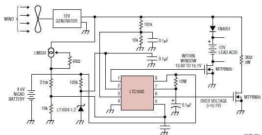
This simple wind charger circuit project is designed using the LTC1042 monolithic CMOS window comparator, manufactured by Linear Technology. The wind charger circuit utilizes wind power to generate the energy necessary for charging Ni-Cd or lead-acid batteries. When the...
Warning: include(partials/cookie-banner.php): Failed to open stream: Permission denied in /var/www/html/nextgr/view-circuit.php on line 713
Warning: include(): Failed opening 'partials/cookie-banner.php' for inclusion (include_path='.:/usr/share/php') in /var/www/html/nextgr/view-circuit.php on line 713