
Donald Smith Devices too good to be true 14
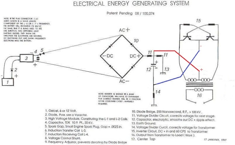
The resonant frequency of an inductor-capacitor (LC) circuit is a critical parameter that determines its performance in various electronic applications, particularly in radio frequency (RF) circuits. In this case, the inductor L2 has a natural resonant frequency of 31.5 MHz. This frequency is the point at which the inductive reactance and capacitive reactance are equal, resulting in maximum voltage across the circuit and minimal current flow.
To calculate the resonant frequency (f) of an LC circuit, the formula used is:
f = 1 / (2π√(LC))
Where:
- f is the resonant frequency in hertz (Hz),
- L is the inductance in henries (H),
- C is the capacitance in farads (F).
In this scenario, the 40K value refers to a resistance or possibly a capacitance value that has been determined through the use of an LC meter. An LC meter is an essential tool for measuring the inductance (L) and capacitance (C) of components in a circuit. By applying the principles of resonance, the LC meter can accurately gauge these values, enabling the calculation of the resonant frequency.
Understanding the relationship between inductance, capacitance, and resistance is crucial for designing circuits that operate efficiently at specific frequencies. The choice of components must be made carefully to ensure that the resonant frequency aligns with the intended operational frequency of the circuit, especially in applications such as oscillators, filters, and RF amplifiers.Originally Posted by kajunkreations The natural resonant freq of the L2 is 31.5 mhz. I calculated the 40K by using LC meter and LC resonance.. 🔗 External reference
Related Circuits
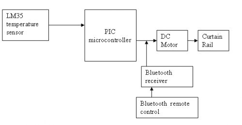
The circuit is designed for a DC motor and Bluetooth system, where the Bluetooth remote control is utilized to open and close curtains. A block diagram is provided for reference. A mobile phone can be used to develop a...

Thank you for the valuable information. I have rewatched all your videos, particularly the ones by Lenz and Znel, and I created a schematic based on my understanding. A schematic is a representation of an electrical circuit that illustrates the...
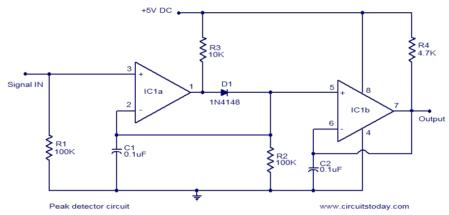
LM339-based peak detector circuit. Simple and easy to construct. Operates from a 5V DC single supply. LM339 is a dual comparator. The LM339-based peak detector circuit is designed to capture and hold the peak value of an input signal. This...
The decision to use electric power was made due to its quieter operation, lack of odor, and ease of carrying the bike up a flight of stairs. The selected conversion kit is manufactured by Currie. Although factory service is...

A simple two-transformer, four-germanium-diode ring modulator featuring a true bypass switching scheme. It includes an input for carrier wave modulation. Power is only required for the status LED. The described circuit is a two-transformer, four-germanium-diode ring modulator, which is a...
The MAX5953A offers a straightforward, cost-effective, and comprehensive non-isolated power integrated circuit (IC) solution for Powered Devices (PD) in Power-over-Ethernet (PoE) systems. The MAX5953A is designed to facilitate the implementation of Power-over-Ethernet applications by providing an efficient means of...