
True Bypass Passive Ring Modulator

The described circuit is a two-transformer, four-germanium-diode ring modulator, which is a type of analog signal processing device used to create amplitude modulation. The circuit typically operates by mixing two input signals: a carrier wave and a modulating signal. The modulation occurs through the use of diodes arranged in a ring configuration, which allows for the generation of sidebands that contain the information from the modulating signal.
In this design, two transformers are utilized to couple the input signals to the diode ring. Each transformer serves to isolate the input signals and ensure proper impedance matching, which is crucial for maintaining signal integrity. The four germanium diodes are arranged in a ring topology, which enables the modulation of the carrier wave by the input signal effectively. Germanium diodes are favored in such applications due to their low forward voltage drop and fast switching capabilities, which contribute to better performance in high-frequency applications.
The true bypass switching scheme integrated into the modulator allows for the signal to be routed around the modulator circuit when it is not in use. This feature is essential for preserving the original signal quality and avoiding any unwanted coloration when the modulator is bypassed. The switching mechanism can be implemented using a mechanical switch or a relay, depending on the design requirements.
Power supply requirements for this circuit are minimal, as power is only needed for the status LED, which indicates the operational state of the modulator. This design consideration enhances its usability in various applications, particularly in live sound environments or studio settings where power conservation is often a priority.
Overall, this two-transformer, four-germanium-diode ring modulator is a versatile tool for audio processing, capable of producing complex modulation effects while maintaining a straightforward design and ease of use.A simple 2 Transformer, 4 Germanium Diode Ring Modulator with a true bypass switching scheme. Includes input for Carrier Wave modulation. Power is only required for the status LED. 🔗 External reference
Related Circuits
This circuit employs two signal generators to simulate an amplitude-modulated RF carrier wave. The output can be utilized to analyze the response of LC and tank circuits. One signal generator represents a high-frequency RF carrier at 200 kHz (VG2),...
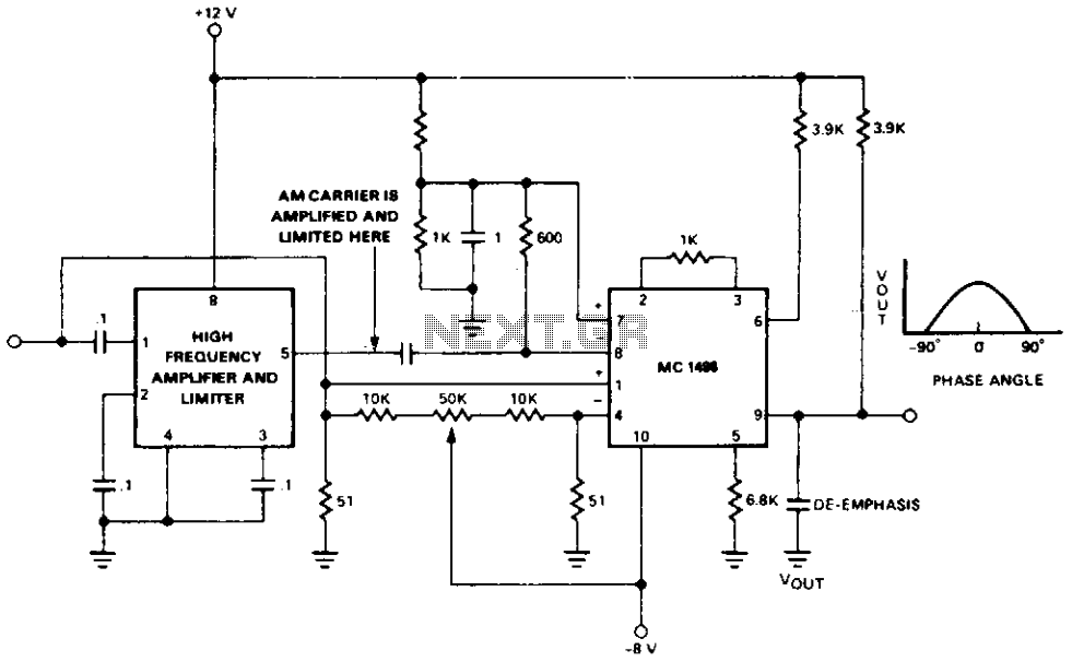
Amplifying and limiting the AM carrier is achieved through the IF gain block, which provides a gain of 55 dB or higher with a limiting level of 40 µV. The limited carrier is then fed to the detector at...
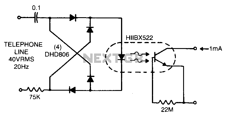
Low line current loading is provided by the H11BX522 photodarlington optocoupler, which delivers a 1 mA output from a 0.5 mA input. The H11BX522 is a photodarlington optocoupler that is designed to provide electrical isolation between its input and output...
This is a simple and cost-effective inverter designed to power a small soldering iron (25W, 35W, etc.) in situations where a mains supply is unavailable. The circuit utilizes eight transistors. The inverter circuit operates by converting DC voltage from a...
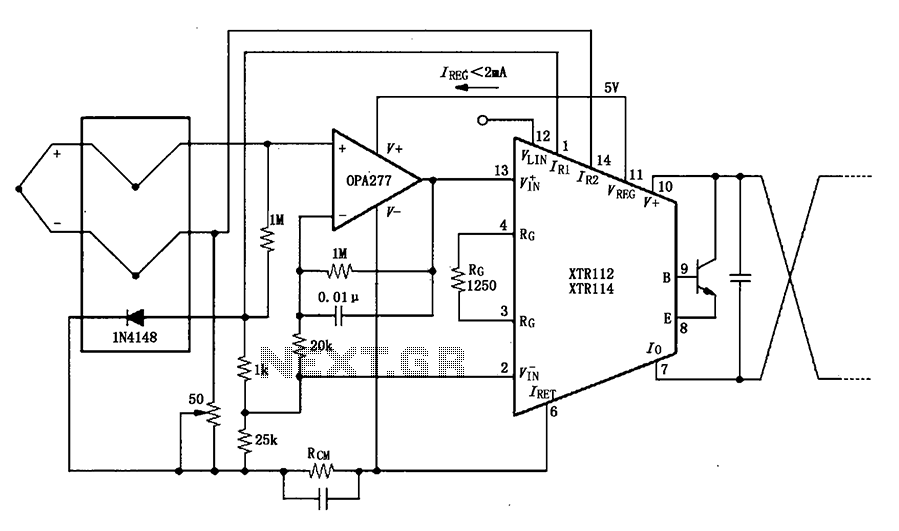
The OPA277 is configured as an inverting amplifier. This inverting amplifier utilizes high input impedance characteristics to minimize loop thermocouple offset drift. A 50-ohm potentiometer is included for calibration, allowing for the adjustment of the inverting input of the...
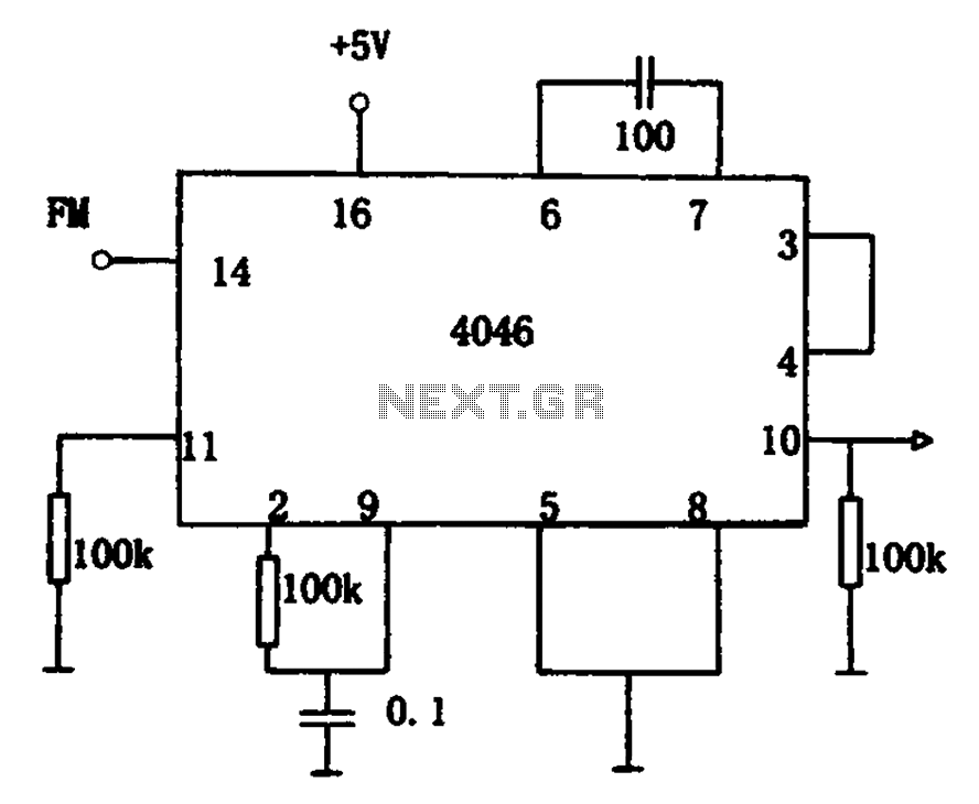
The circuit utilizes the 4046 Phase-Locked Loop (PLL) for FM demodulation, incorporating an intermediate frequency (IF) FM demodulation output based on the input signal frequency. The 4046 PLL is a versatile integrated circuit that can be configured for various applications,...
Warning: include(partials/cookie-banner.php): Failed to open stream: Permission denied in /var/www/html/nextgr/view-circuit.php on line 713
Warning: include(): Failed opening 'partials/cookie-banner.php' for inclusion (include_path='.:/usr/share/php') in /var/www/html/nextgr/view-circuit.php on line 713