
Door Bell Chime Project
The circuit design for the doorbell chime utilizes the versatile 555 timer IC, configured in astable mode to generate an audible tone when the pushbutton switch is activated. The 555 timer serves as an oscillator, producing a square wave output that drives the connected speaker.
The schematic includes five resistors which are strategically placed to set the timing characteristics of the 555 timer. These resistors work in conjunction with the four electrolytic capacitors to determine the frequency and duty cycle of the output waveform. The ceramic capacitor is used for stability and noise filtering, ensuring a clean signal is delivered to the speaker.
Three diodes are incorporated into the design to protect the circuit from reverse polarity and to manage the flow of current, particularly when the pushbutton is engaged. The pushbutton switch acts as the user interface, allowing for manual activation of the chime. When pressed, it completes the circuit, triggering the 555 timer and producing sound through the speaker.
The power supply for the entire circuit is provided by a 9V battery, which ensures adequate voltage for the operation of the 555 timer and the speaker. This simple yet effective design allows for customization, such as adjusting the tone or volume by modifying component values, making it an ideal project for electronics enthusiasts.Build Your Own Door Bell Chime using 555 timer integrated circuit, a speaker, 5 resistors, 4 electrolytic capacitors, 1 ceramic capacitor, 3 diodes, 1 pushbutton switch and 9 V battery as power supply.. 🔗 External reference
Related Circuits
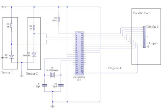
The dual-channel thermometer is a simple project based on a PIC microcontroller with ADC capabilities. It is an inexpensive thermometer that utilizes low-cost components and does not require high-sensitivity or expensive sensors. Instead, it employs a simple silicon diode...
Automatic door control systems typically have a high market price for finished products. The proposed method is suitable for home use, utilizing easily accessible components. This design is ideal for those interested in creating their own automatic door system....
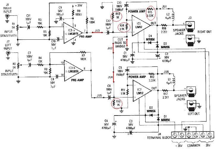
The LM12 audio amplifier circuit is designed to deliver high output power for 8 ohm or 4 ohm load impedances. The maximum output power provided by the LM12 audio amplifier is approximately 60 watts for a 4 ohm load...
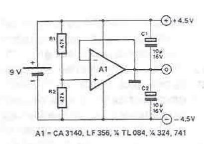
A symmetrical power supply can be designed using this circuit diagram. This symmetrical power supply is constructed with a simple operational amplifier and some classic electronic components. Resistors R1 and R2 form a high impedance voltage divider. The operational...
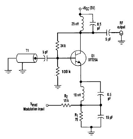
This varactorless high-frequency modulator electronic project must be powered by a simple DC 3-volt power source, such as a 3-volt battery. Traditionally, high-frequency oscillators are frequency-modulated using a varactor. However, varactors typically require a significant voltage change to achieve...
To put the relay in tension the 4 buttons S1 S4 must be pressed. If anyone of the 4 buttons S5 S8 are pushed the relay doesn't tension (doesn't receive supply voltage). The supply voltage must be equal to...