
Homemade infrared automatic door controller circuit
The automatic door control system utilizes a combination of infrared technology and remote control mechanisms to facilitate the opening and closing of doors based on human presence. The core of the system consists of an infrared emitter and receiver, which form a beam that, when interrupted, triggers the door's motor to open. The infrared emitter is housed in a 60mm long tube, which is aligned parallel to the door at a specified height. This alignment is crucial to ensure that the emitted infrared light is accurately received by the detector.
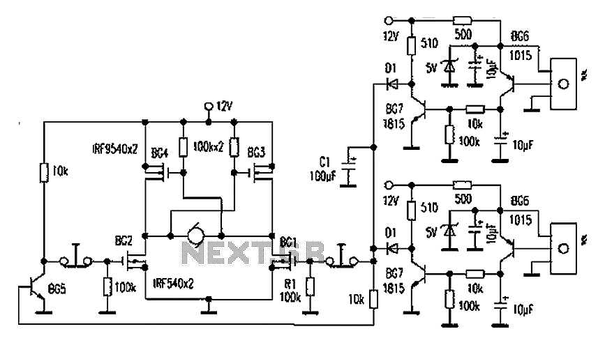
The circuit design features several key components, including transistors for signal amplification and filtering. Specifically, transistors BG6, BG7, and BG5 are employed to manage the motor's operation, with BG2 and BG3 facilitating the closing action when the infrared signal is intact. The system is designed to be responsive; when an individual approaches the door, the interruption of the infrared beam causes the output of BG7 to rise, activating the motor through BG1 and BG4, thus opening the door.
The motor driving circuit utilizes high-performance power transistors, such as the IRF9540 and IRF540, which are capable of handling substantial current and voltage with minimal power loss. This efficiency is essential for maintaining low operational costs and ensuring the longevity of the system. The chosen motor, a 12V auto wiper motor, is modified to suit the application by removing its arm and integrating it with a gear system from a four-stroke motorcycle engine, ensuring sufficient torque for door operation.
Safety features are integrated into the design, including a step-down transformer that isolates the main circuit from the mains supply, reducing the risk of electrical hazards. The system is powered by a 12V battery, ensuring that it remains operational even during power outages.
In conclusion, this automatic door control system represents a cost-effective and efficient solution for homeowners looking to implement automated entry systems. With careful component selection and a focus on safety and functionality, this design is both practical and innovative, allowing for customization and ease of assembly. Automatic door control and the market price of finished executing agency generally high, the proposed method will be suitable for homemade use, the components used are easy to find those who are interested to try not imitation original: New house installed aluminum sliding doors, and finally a chance to give their own design an automatic door. Human detection part household appliances remote control transmitter receiver technology, unaffected by ambient light.
Figure 1 is an infrared receiver and the motor drive circuit, when no one in the infrared receiver normally receives from the other side sent over an infrared beam. With just 60mm long tube inserted into the guide tube infrared emission (Fig. 3) on the wall parallel to the fixed, appropriate height and alignment and receiver opposite the infrared emitted by such a bunch, easily interfere with another receiver.
Specific installation methods shown in Figure 4. After BG6, BG7, CR and other amplified and filtered output low, this time off BG5, BG2, BG3 conduction execute closing action. When people went to the door, the infrared light is blocked, BG7 output high limit switch drive all the way through BG1, BG4 door opening action, the other passing R1 drive BG5 to BG2 off, when the door opened the door to a specified position limit switch off the motor no longer continue to operate.
When people leave, BG7 no longer high output, via a capacitor C1 Latency closing action after three seconds. TV remote control transmitter circuit can be finished restructuring (Fig. 2), remove the original launch tube connected by wires to the ready special launcher, two transmitters in parallel and note polarity.
Then find a suitable key to short-circuit it, it has been emitted, preferably a screen key, in order to try not to interfere with possible radiation in the TV area. RW with transmit power adjusted to just to be able to receive as well. The main component selection: the motor driving circuit power transistors is four IRF9540/P type/100V/19A and FET IRF540/N type/100V/28A, since it is voltage driven, driving power is hardly consumed.
Its internal resistance, temperature rise is small, they can be mounted on a small piece of aluminum, and pay attention to insulation. The motor can go to the store to buy a 12V auto wiper motor, remove its arm, fitted with a four-stroke motorcycle engine gears, pick up a few small chains, and then use a steel plate to make a bracket on the door, specific installation methods shown in Figure 5.
In order to prevent the normal use of power door impact, so I designed a step-down transformer coupled with a 12V battery, main circuit 12V power supply, mains isolation, increased safety.
Related Circuits
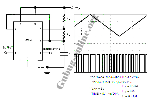
This design circuit for a pulse position modulator can be easily constructed using a 555 integrated circuit (IC). The pulse position modulator modulates the on-period while maintaining a fixed off-period. The circuit utilizes the 555 timer IC in astable mode...
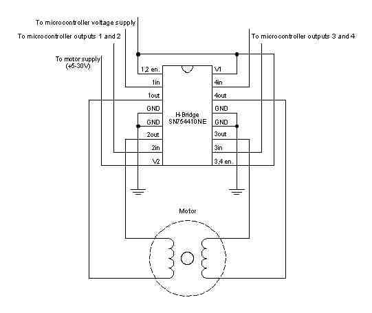
A stepper motor is a motor controlled by a series of electromagnetic coils. The center shaft has a series of magnets mounted on it, and the coils surrounding the shaft are alternately energized or de-energized, creating magnetic fields that...
As shown in the figure, the 555 timer, resistors R1, RP1, and capacitor C1 form a controlled audio oscillator. The frequency of the oscillator is given by the formula f = 1.44 / ((R1 + 2 * RP1) *...
A telephone line-based audio muting and light activation circuit. Frequently, when listening to music or watching television at elevated volume levels, it becomes difficult to hear a telephone ring, resulting in missed important calls. This circuit is designed to address...
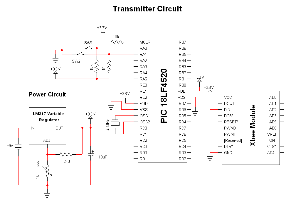
The advantage of these compact Xbee modules is that they handle most of the complex tasks. The transmitter and receiver circuits are both straightforward. The primary components in the circuit include the Xbee Modules, PIC 18LF452, and LM317. Both...
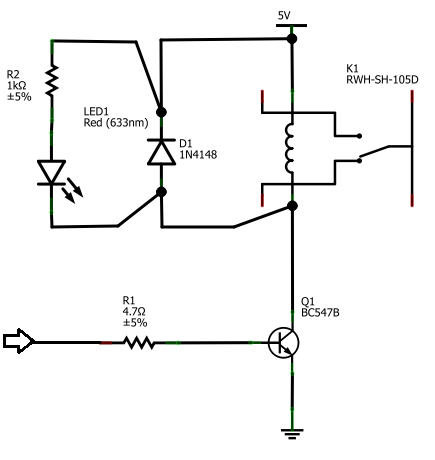
The BC547B transistor has a collector-base voltage (Vcbo) of 50V, a collector-emitter voltage (Vceo) of 45V, and an emitter-base voltage (Vebo) of 6V. In contrast, the BC548 transistor in the original circuit has a Vcbo of 30V, a Vceo...
Warning: include(partials/cookie-banner.php): Failed to open stream: Permission denied in /var/www/html/nextgr/view-circuit.php on line 713
Warning: include(): Failed opening 'partials/cookie-banner.php' for inclusion (include_path='.:/usr/share/php') in /var/www/html/nextgr/view-circuit.php on line 713