
Door handle alarm

The automatic door handle alarm circuit is designed to enhance security by providing a simple yet effective alert system. The circuit operates on a dual principle: it detects human presence through capacitive coupling and generates an alarm output. The configuration of Q1 as an astable multivibrator allows for the generation of a square wave signal, which is critical for the operation of the circuit. The oscillations produced by Q1 are dampened when the handle is touched, altering the biasing conditions of Q2, which is crucial for the subsequent actions of Q3 and the LED.
In the context of the circuit, Q2 acts as a switch that controls the state of Q3. The transition from an oscillating state to a stable state when the handle is touched ensures that the LED lights up, providing a visual indication of the alarm state. The inclusion of the latching transistor pair Q4 and Q5 allows the circuit to maintain the alarm state even after the initial trigger event (the touch) has ceased, ensuring that the buzzer Z1 continues to sound until a manual reset is performed via switch S2.
The design also incorporates an inductor L1, which plays a role in tuning and stabilizing the circuit's response. The specification of winding 25 turns of 0.4 mm enameled copper wire around resistor R2 serves a dual purpose, providing both resistance and inductance in a compact form factor. This design choice is efficient and minimizes the number of components required, which is advantageous for space-constrained applications.
Overall, this automatic door handle alarm circuit is a practical solution for alerting individuals to unauthorized access or unwanted touching of door handles, making it suitable for various security applications in residential, commercial, and industrial settings.The automatic door handle alarm circuit gives a audible alarm and glows a LED when somebody touches the handle of the door. The circuit is latching type and continues to produce sound until it is switched off. The transistor Q1 is wired as an astable multivibrator whose output is used to bias transistor Q2 to conduction.
As a result the transistor q 3 and LED are in OFF state. When someone touches the handle, the capacitance of the human body damps the the oscillations of Q1. The cuts the biasing of Q2 and it goes OFF. As a result the current flows to the base of Q3, it conducts and LED glows. If the switch S1 is ON the transistor pairs Q4&Q4 which is wired in the latching mode is triggered and the Buzzer Z1 is activated. When the person removes his hand from door handle the LED goes OFF but the buzzer continues to beep. The only way to mute the buzzer is to open the switch S2. To make L1 wind 25 turns of 0. 4 mm enameled copper wire on resistor R2 and solder the ends of the wire to the resistor leads. This unit will stand for the R2 as well as L1 because both are parallel in the circuit. 🔗 External reference
Related Circuits

This circuit serves as an alarm system suitable for both home security and personal belongings such as handbags. When installed in a home, it can be positioned on doors or windows, and when used for bags, it provides a...
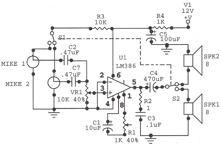
The LM386 is an ideal choice for a door phone application. This device is particularly beneficial in modern urban households, utilizing a condenser microphone and a speaker. The LM386 is a low-voltage audio power amplifier that is commonly used in...

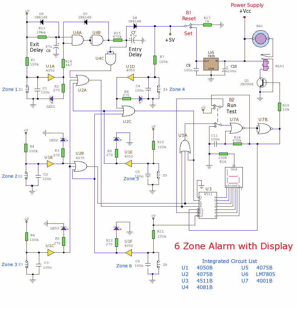
This circuit is capable of generating up to 1 W of audio power to drive a speaker or horn. When the CDS cell is exposed to light, its resistance decreases, activating NOR gate (a). This activation causes gates (a)...
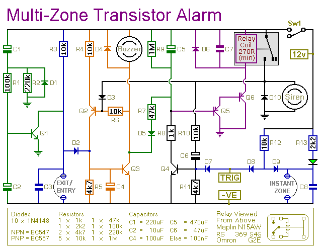
This transistor-based alarm features automatic exit and entry delays, along with a timed bell cut-off and system reset. In addition to the exit/entry zone, the basic alarm board includes one instant zone, which is sufficient for many applications. However,...

The circuit utilizes a 555 integrated circuit (IC). When an incoming call is received, 220 V AC is stepped down through resistor R1, followed by rectification using diode VD1. A voltage regulator (DW) is employed, and capacitor C2 is...
This section includes intruder alarms for homes, cars, and motorcycles, as well as power failure alarms, water level alarms, and a snore detector. All circuits are organized alphabetically on the Circuit Index page and chronologically on the update page....