
Door open alarm

This design incorporates a TLC555 monostable timer circuit. The 1 µF capacitor and 5.1 ohm resistor connected to pins 6 and 7 establish the monostable RC time constant, allowing the LED and piezo alarm to remain activated for about five seconds when triggered. A distinctive feature of this circuit is its triggering method. Typically, a 555 timer circuit is activated by bringing the trigger (pin 2) low, which generates a high output at pin 3. In this configuration, when the door is closed, the TL3019 output remains low. The trigger pin 2 is connected to the supply voltage (Vcc). When the door opens, a positive high pulse is sent to control pin 5 through a 0.1 µF capacitor, which also resets pin 4. This initiates the timing cycle, activating both the piezo alarm and the LED visual indicator.
The door open alarm circuit operates effectively by integrating various components to ensure reliable performance. The TL3019 Hall-effect sensor detects the presence of a magnetic field and generates a low output signal when the door is closed. Upon opening the door, the magnetic field is interrupted, causing the sensor to output a high signal. This transition triggers the TLC555 timer.
The TLC555 timer is configured in monostable mode, where it produces a single output pulse in response to a triggering event. The time period for which the output remains high is determined by the resistor-capacitor (RC) network connected to pins 6 and 7. In this case, the 1 µF capacitor and 5.1 ohm resistor create a time constant that allows the LED and piezo alarm to activate for approximately five seconds.
The piezo alarm provides an audible alert, while the LED serves as a visual indicator, enhancing the user’s awareness of the door's status. This dual notification system is particularly useful in environments where immediate attention may be required. The circuit is designed to be energy-efficient, as the alarm and indicator are only activated when necessary.
In summary, the door open alarm circuit effectively combines a Hall-effect sensor, a monostable timer, and output indicators to provide a reliable solution for detecting door positions in various applications. The design is straightforward, making it suitable for integration into automotive, industrial, and household appliances.Door open alarms are used chiefly in automotive, industrial, and appliance applications. This type of circuit can sense the opening of a refrigerator door. When the door opens, a triac could be activated to control the inside light. The figure shows a door position alarm. When the door is opened, an LED turns on and the piezo alarm sounds for approximately 5 seconds. This circuit uses a TL3019 Hall-effect device for the door sensor. This normally open switch is located in the door frame. The magnet is mounted in the door. When the door is in the closed position, the TL3019 output goes to logic low, and remains low until the door is opened. This design consists of a TLC555 monostable timer circuit. The 1 µ¥ capacitor and 5.1 ohm resistor on pins 6 and 7 set the monostable RC time constant. These values allow the LED and piezo alarm to remain on about 5 seconds when triggered. One unusual aspect of this circuit is the method of triggering. Usually a 555 timer circuit is triggered by taking the trigger, pin 2, low which produces a high at the output, pin 3. In this configuration with the door in the closed position, the TL3019 output is held low. The trigger, pin 2, is connected to Vi the supply voltage Vcc. When the door opens, a positive high pulse is applied to control pin 5 through a 0.1 µ¥ capacitor and also to reset pin 4.
This starts the timing cycle. Both the piezo alarm and the LED visual indicator are activated. 🔗 External reference
Related Circuits

The motorcycle anti-theft alarm described in this article utilizes a proprietary displacement sensor. It is characterized by high sensitivity, good reliability, a low false alarm rate, and ease of construction. The principle of the circuit involves an integrated vibration...

A simple alarm circuit with a diagram and schematic that generates a multi-tone sound. This alarm circuit is suitable for use in burglar alarms and sirens and is designed using dual op-amps MC1458 and LM380. The described alarm circuit utilizes...
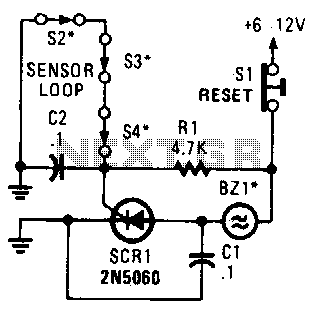
A string of three series-connected, normally closed switches is connected across the gate of a silicon-controlled rectifier (SCR). When one switch opens, the SCR is triggered through resistor R1, activating an alarm. The alarm is designed to be of...

This is an enhanced version of the simple Garage/Shed Alarm. The entry and exit delays have been increased to approximately 30 seconds, and a timed siren cut-off and automatic reset have been added. The LED has been replaced with...

This circuit utilizes invisible infrared light to detect the movement of individuals passing through a doorway. A short beep is produced when the infrared beam is interrupted. The circuit operates by employing an infrared transmitter and a receiver. The transmitter...

The operation of a 303MHz circuit has been covered in our project WIRELESS DOORBELL. We are not going over how the circuit works but explain the importance of some of the components and how they affect the range. The...