
Invisible Infrared Alarm Circuit

The circuit operates by employing an infrared transmitter and a receiver. The transmitter emits infrared light, which is typically invisible to the human eye. This light is directed across the doorway to the receiver located on the opposite side. When an individual walks through the door, they obstruct the infrared beam, causing a disruption in the light signal received by the sensor.
The receiver is often a photodiode or phototransistor, which detects the intensity of the incoming infrared light. When the beam is broken, the output of the photodiode changes, triggering a signal to a microcontroller or a simple comparator circuit. This signal is then processed to activate a sound-generating component, such as a piezo buzzer or speaker, which emits a short beep to indicate the presence of movement.
Additionally, the circuit may include components such as resistors to limit current, capacitors for signal smoothing, and possibly a microcontroller for more advanced processing and features, such as adjustable sensitivity or delay times. Power supply considerations are also essential; the circuit can be powered by batteries or an external power source depending on the application requirements.
Overall, this infrared motion detection circuit is a practical solution for security and automation applications, providing a simple yet effective means of detecting movement and alerting users accordingly.This circuit uses Invisible Infrared light to detect the movement of people through the door. A short beep will be generated when the infrared beam breaks 🔗 External reference
Related Circuits
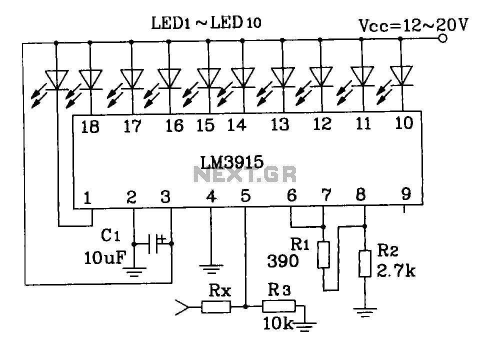
This document describes a simple LM3915 audio power meter circuit diagram. It notes that if the internal resistance of the speaker is 4 ohms, a resistor value of 10k ohms should be used for Rx. For an 8-ohm speaker,...
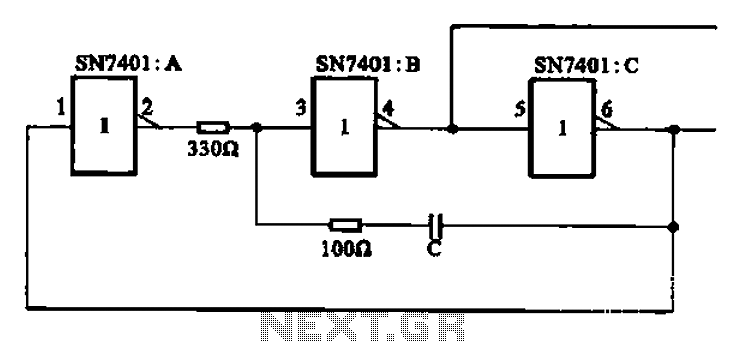
The clock signal generating circuit utilizes an RC configuration, commonly applicable in most TTL systems. This circuit requires a set of six inverters, specifically three inverters from the SN7401 series. The clock frequency is determined by the values of...

This project involves the construction of a VHF-UHF linear amplifier capable of operating at frequencies ranging from 47 MHz to 740 MHz. It serves as the final output stage for any transmitter functioning within these frequencies. The amplifier utilizes...
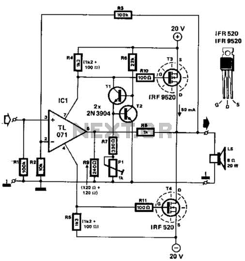
Two complementary MOSFETs are utilized to deliver 20 W into an 8-ohm load. A TL071 operational amplifier serves as the input amplifier. The MOSFETs must be equipped with a heatsink that has a thermal resistance of better than 5...
This circuit provides a straightforward and efficient method for interfacing two relays in switching applications. The relay driver utilizes a standard BC547 NPN transistor (or equivalent) to enhance the input impedance. It is a widely used driver capable of...
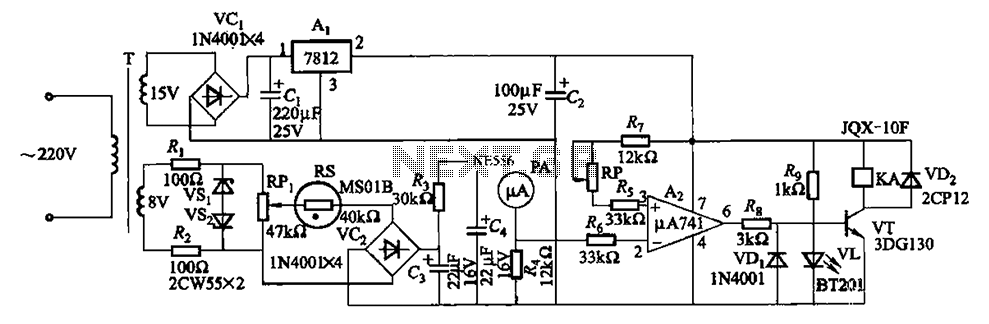
The humidity alarm system is based on integrated circuits and relays, utilizing the pA741 circuit. The MS01 employs a wet-type humidity resistance element as a probe. When the humidity exceeds a predetermined value, specifically set at 6 feet high,...