
Closed-Loop Alarm Circuit
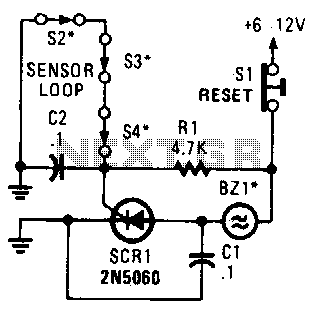
This circuit configuration utilizes three normally closed switches, which are connected in series. The arrangement ensures that the SCR remains off under normal operating conditions. Each switch acts as a safety mechanism; if any one of the switches is opened, it allows current to flow through R1 to the gate of the SCR, thereby triggering it. The SCR, once triggered, allows current to pass through to the alarm, which is designed to be noninterrupting. This means that the alarm will sound continuously without interruption until the circuit is reset or power is removed.
The use of a noninterrupting alarm is critical in applications where continuous monitoring is essential. The alarm can be an audible signal, such as a buzzer or siren, ensuring that the activation is noticeable. The resistor R1 plays a crucial role in limiting the gate current to the SCR, protecting it from excessive current that could damage the component. The design must also consider the voltage and current ratings of all components involved, ensuring that they can handle the load without failure.
In practical applications, this circuit can be used in various safety systems, such as intrusion detection or equipment monitoring, where the opening of any switch indicates a fault condition or unauthorized access. The series connection of the switches adds a layer of redundancy; all switches must remain closed for the SCR to remain inactive, thereby enhancing the reliability of the system. Proper placement of the switches and selection of the alarm type are essential to ensure effective operation in the intended environment. A string of three series-connected, normally closed switches are connected across the gate of an SCR. When one opens, the SCR triggers via Rl, sounding an alarm. The alarm should be of the noninterrupting type. 🔗 External reference
Related Circuits

A ringer interface circuit is designed to buffer the output of a central telephone system, which connects to multiple ringers distributed throughout a building. This circuit addresses an issue where the line overloads when ringing, requiring a reset. The...

555 Timer with Audio Alarm Circuit. This circuit serves as a straightforward electronic timer equipped with an audio alarm feature. The 555 timer is a versatile integrated circuit widely used in various timer, delay, pulse generation, and oscillator applications. In...
The schematic presented is a project for a simple temperature sensor circuit, also referred to as a heat sensor circuit, which activates an LED in response to heat. The circuit is straightforward to construct and requires only a few...

This circuit utilizes inexpensive, commonly available components to generate a precise dial tone for telephone applications. The Intel 82C54 timer-counter (U1) produces square wave signals at frequencies of 350 Hz and 440 Hz, which are subsequently filtered by resistors...

The schematic for this project is extensive, and the complete schematic is displayed below. It is divided into two sections: the analog and digital sections. The schematic illustrates the analog-to-digital conversion circuit, which includes 12 comparators—6 for the X-axis...
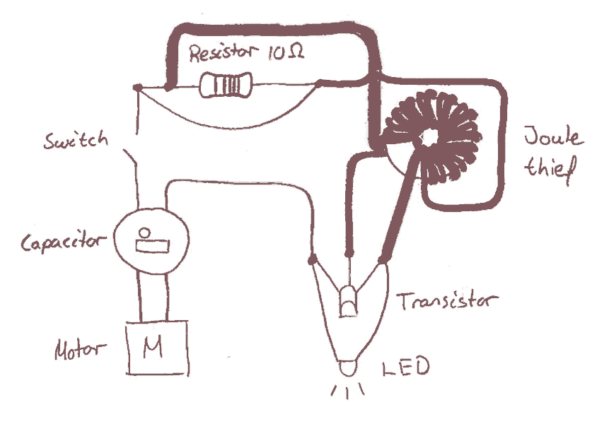
Early in the electronics design process, the decision was made to implement a joule saver in the circuit. The intention of using a joule saver is to maintain the LED light illumination even after the handle is no longer...
Warning: include(partials/cookie-banner.php): Failed to open stream: Permission denied in /var/www/html/nextgr/view-circuit.php on line 713
Warning: include(): Failed opening 'partials/cookie-banner.php' for inclusion (include_path='.:/usr/share/php') in /var/www/html/nextgr/view-circuit.php on line 713