
Enhanced Alarm
The enhanced Garage/Shed Alarm circuit is designed to provide an effective security solution for garages and sheds, leveraging modern electronic components to ensure reliability and ease of use. The integration of a timed siren cut-off and automatic reset feature enhances its functionality, allowing for a user-friendly experience. The use of normally-closed input devices ensures compatibility with a wide range of sensors, making the alarm adaptable to various security needs.
The power supply versatility of the circuit allows it to operate efficiently on different voltage levels, catering to both mains and battery-powered applications. The choice of a 9-volt battery as a standard in the schematic exemplifies the design's intent for portability and low power consumption. The alarm’s operational logic is straightforward, with clear indications through the buzzer when the system is armed or triggered.
The design incorporates a relay that plays a crucial role in activating the siren upon alarm trigger. The timed reset functionality is particularly beneficial in preventing false alarms, ensuring that the system remains functional without requiring constant manual intervention. The circuit's ability to self-reset every five minutes if the trigger is not restored adds a layer of resilience, providing ongoing protection.
The choice of the CMOS 4093 is significant due to its superior performance characteristics, specifically the hysteresis property that enhances noise immunity and stability in the circuit's operation. This is particularly important in environments where electrical interference may be present. The ability to adjust the timing components (R5, R6, and R7) allows for fine-tuning of the alarm's response times, making it customizable to the user's specific requirements.
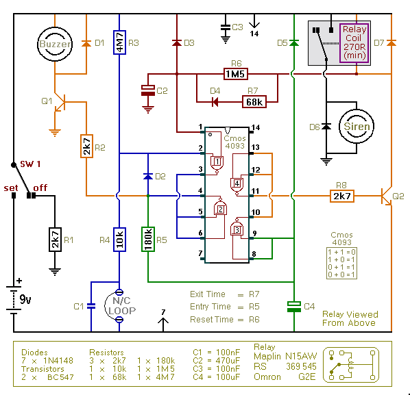
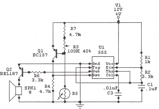
Overall, this alarm circuit represents a well-thought-out design that balances functionality, adaptability, and ease of use, making it an excellent choice for enhancing security in various applications. The inclusion of comprehensive support materials further aids users in understanding and constructing the circuit effectively.This is an enhanced version of the simple Garage/Shed Alarm. The Entry and Exit delays have been increased to about 30-seconds - and I`ve added a timed Siren cut-off and automatic Reset. I`ve also replaced the LED with an entry Buzzer. These enhancements mean that the new version will have a much wider application. The circuit is designed to be u sed with the usual types of normally-closed input devices such as - magnetic-reed contacts - micro switches - foil tape - and PIRs. Although it can be mains powered - the extremely small standby current makes it ideal for battery-powered operation.
I`ve used a 9-volt battery in the diagram - but the circuit will work at anything from 5 to 15-volts. Just choose a Relay, Buzzer and Siren suitable for the voltage you want to use. To set the alarm - move SW1 to the "set" position. You now have about 30 seconds to leave the building. When you return and open the door - the Buzzer will sound. You then have about 30 seconds to move SW1 to the "off" position. If you fail to do so - the relay will energize and the Siren will sound. After about 10-minutes the alarm will attempt to reset itself. If the trigger circuit has been restored - the attempt will be successful. But if the loop is still open - the attempt will fail - and the alarm will re-activate. The circuit will go on trying to reset itself about every five-minutes thereafter - until the trigger circuit has been restored - or the alarm is switched off.
If a 1M5 resistor is not available - use a 1M and a 470k resistor connected in series. That`s what I did. Because of manufacturing tolerances - the precise length of any delay depends on the characteristics of the actual components you`ve used in your circuit. But by altering the values of R5, R6 & R7 you can adjust the Entry, Reset & Exit times to suit your requirements.
Increasing the values increases the time - and vice-versa. The circuit works best with a Cmos 4093. The Cmos 4093 is the Schmidt-Trigger version of the 4011. While its logic is identical to that of the 4011 - what makes it different is a property known as "Hysteresis". The circuit will work with a 4011. But - because the 4011 does not posses hysteresis - it will not work as well. The Support Material includes an explanation of hysteresis - a complete circuit description - a parts list - a step-by-step guide to construction - and more.
🔗 External reference
Related Circuits
This circuit includes automatic exit and entry delays along with a timed bell cut-off. It accommodates both normally-closed and normally-open contacts and features a 24-hour personal attack/tamper zone. The circuit is permanently connected to a 12-volt supply, and its...
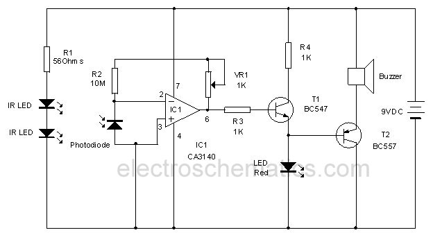
This circuit utilizes invisible infrared light to detect the movement of individuals through a doorway. A brief beep will be emitted when the infrared beam is interrupted. The infrared movement detection circuit employs an infrared LED and a photodiode or...
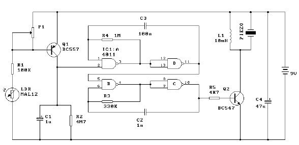
This light alarm schematic circuit is designed using common electronic components, as illustrated in the circuit diagram below. The light alarm circuit will activate an alarm as soon as the drawer is opened and light falls on the Darlington...
The IC 555 Light Alarm (Sun Up Alarm) is a circuit designed to emit a loud alarm at dawn, particularly beneficial for individuals who struggle to wake up even with a traditional alarm clock. The circuit can be modified. The...

Emits a beep if the door remains open for more than 20 seconds. This circuit is housed in a compact enclosure and is positioned in the refrigerator near the lamp or the opening. The described circuit functions as a door...
High Power Siren Circuit. This article discusses a robust siren circuit suitable for various applications. A complementary transistor pair (BC557 & BC337) is configured as an oscillator to directly drive the speaker. Transistor Q1 (BC557) is utilized to ensure...